DOOR LOCKS AND KEYS
KEYS
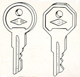
Two sets of keys [were] furnished with each new car. The keys with the round handles fit the igniton and front door locks. The keys with the octagonal shaped handles fit the locker box door and rear compartment lock. All keys are numbered and these numbers shoud [have been] registered on your Owner Identification Card as well as some other suitable place for reference should the keys become lost. New Keys [could have been] otained from your Hudson Dealer only by key number.
|
FIGURE 1
 |
TO UNLOCK CAR
To unlock door, isnert key with round handle fully in the door lock cylinder and turn lock one-quarter turn to the left, then return key to vertical position and remove. Should it be difficult to insert the key due to moisture freezing in the lock in cold weather, heat the key with a match or lighter and insert it into the lock. Repeat several times if necessary until the key can be turned.
|
FIGURE 2
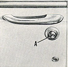 |
TO LOCK CAR
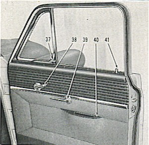
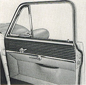
Close windows, push inside safety buttons (41, Figure 3) down on all doors except the front door from which you are leaving. Clsoe the front door, isnert key n lock and turn key one-quarter turn to the right until safety button is down to locked position. Turn key back to the vertical position and remove key. Push in on button (A, Figure 2) to insure that door is locked. Rear doors amy also be locked by pressing down buttons while doors are open and then closing doors.
|
FIGURE 3
 |
CAUTION: Always remove the ignition key if the car is to be left unattended even for a few minutes.
TO OPEN DOOR FROM INSIDE:
Front Door: Rotate inside handle (39, Figure 3) by pushing it downward.
Rear Door: Rotate inside handle by pulling it backward.
TO CLOSE DOOR FROM INSIDE: Grasp pull-to handle and arm rest (40) and pull door shut.
NOTE: On the rear doors, the inside safety buttons (41) must be in the "UP" position before the doors can be opened by either the inside or outside handles.
|
REAR COMPARTMENT DOOR
TO UNLOCK: Insert key in lock and turn key one-quarter turn clockwise while exerting slight downward pressure against the compartment door ornament.
TO LOCK: Remove key and close the compartment door with a slight pressure.
|
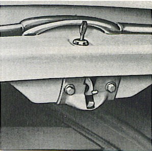 |
HOOD LOCK
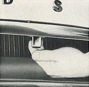
TO RAISE HOOD: Release catch by reaching under the grill louver, pull lever forward and raise hood.
TO LOCK HOOD: Lower the hood and press down firmly on front end.
|
 |
WINDOWS
WINDOW VENTILATING WINDOWS
Friction Type: Wing can be opened by pressing in the small button (Figure at right) and rotating the latch handle upward.
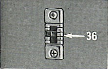
DOOR WINDOWS
The door windows are opened and closed by cranking the regulator handles (38, Figure 3).
|
 |
FRONT SEAT ADJUSTMENTS
Raise the seat adjusting lever located on the lower edge of the front seat near the left side and exert slight body pressure either forward or backward to move the seat on the adjustable seat track for the desired driving position. Releasing the adjusting lever will lock the seat in positin and prevent movement.
|
 |
[The following italicized exerpt is additional information as suggested in Hudson Service Merchandiser Vol. 5, No. 4, April 1953.]
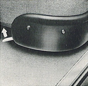
The front seat track assemblies, right and left, of the Hudson Jet [Models] are assembled with the attaching bolts "A" in the center holes of the support brackets. By changing the bolts to the rear or front holes, the track (and front seat) movement range is increased one inch forward or backward.
The front seat tracks provide a seat adjustment range of four inches; however, when assembled in production, a clevis pin "B" is installed in the front end of each track which limits the backward travel to three inches. Note illustration below.

Should the full range of movement be desired ( one additional inch of backward travel). it is only necessary to remove the metal seat cushion shields on the right and left sides; then place the seat in the forward position, which will permit the removal of these clevis pins which are secured by cotter pins.
There are no spacers between the seat track "C" and the car floor of the Jet. The height of the front seat may be increased and the angularity changed (to accomodate owners or prospects) by placing spacer washers between the front and/or rear track brackets and the floor panel as desired.
|
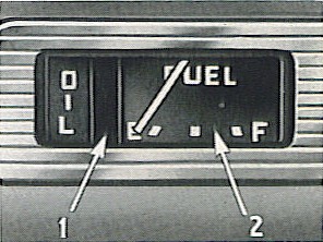
GAUGES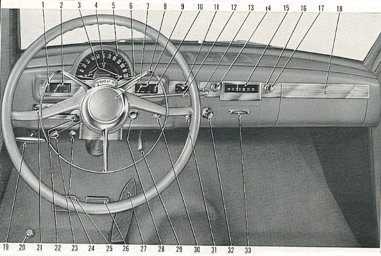
|
(1) OIL PRESSURE INDICATOR
Red light appears when ignition is turned on and engine is not running. If light remains lighted while engine is running, turn off ifnition immediately and determine cause.
(2) FUEL GAUGE
With the ignition key turned either to the left or the running position (right), the gauge hand will show the amount of fuel in the gas tank. When hand reaches "E" empty mark, approximately 1-1/2 gallons of fuel remain in reserve. For further "method of checking" detail and diagnosis, refer to "Gauge Trouble Diagnosis".
|
 |
REMOVAL
- Follow same procedure as for the "Instrument Cluster and Panel Assembly Removal".
- Remove the two screws attaching the fuel gauge to the instrument cluster assembly, disconnect wires and remove the fuel gauge.
INSTALLATION
To install, reverse procedure of removal.
|
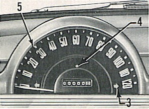
(3) DIRECTION INDICATOR LIGHTS
Arrows indicate right or left hand turn. Light flashes green when turn indicator signals are turned on.
(4) HEADLIGHT BEAM INDICATOR
A small red light will show on the speedometer above the mileage indicator when the headlights are on the high beam.
(5) SPEEDOMETER
The speedometer registers miles per hour and accumulated mileage. Always drive at a safe speed.
|
 |
REMOVAL
- Remove the instrument cluster assembly, follow operations 1 through 8 under "Instrument Cluster and Panel Assembly Removal".
- Snap out speedometer bulb and socket assemblies and disconnect wire for high beam signal light.
- Remove four screws attaching speedometer to instrument cluster panel and one small Philips head screw attaching speedometer head to speedometer bezel and remove the speedometer.
NOTE: It is also necessary to perform the preceeding operations to replace the speedometer lens or the headlight high beam signal bulb. |
 |
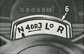
(6) HYDRA-MATIC DRIVE INDICATOR
The indicator located at the top of the steering column shows the position the Hydra-Matic control lever is in. Also see "Hydra-Matic Drive."
|
 |
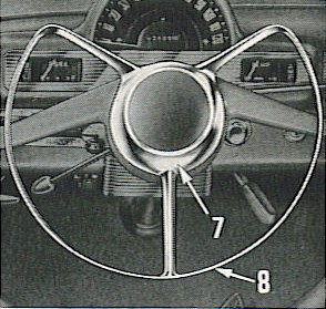
(7) HORN BUTTON
Pressing the horn button will sound the tuned dual horns located in the hood compartment.
(8) HORN RING
Standard on Super Jet Models, optional on Jet Models.
|
 |
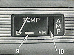
(9) TEMPERATURE GAUGE
Marked "TEMP" indicates the temperature of the coolant in the cooling system when ignition switch is turned either to the left or the running position. Under normal driving and temperature conditions, the pointer will show within the range of the center bar on the dial between the "C" and "H" marks. If the gauge shows a rapid rise to the "H" position, stop and investigate. For further method of checking detail and diagnosis, refer to "Water Temperature Gauge" in the Cooling section.
REMOVAL and INSTALLATION
Follow same procedure as for "Fuel Gauge Removal" and "Installation."
(10) GENERATOR CHARGE INDICATOR
Dial marked "AMP" shows red when ignition is turned on and when engine is running at idle speed. Light should go out as engine speed is increased. For further "method of checking" detail and diagnosis of the constant voltage regulator, refer to "Gauge Trouble Diagnosis".
|
 |
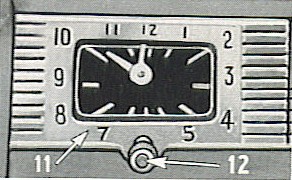
(11) CLOCKS
MECHANICAL: Requires winding every day as there is a heavy mainspring geared to drive the works for approximately thirty hours. Turn knob clockwise to wind.
ELECTRICAL: Electrically wound. A small coil spring is attached to a steel armature limited by design to approximately three minutes of operation. As the armature rotates and the spring runs down a small toggle switch is thrown, exciting an electromagnet that rewinds the armature. This is heard as a sharp "clunk" at each cycle. Otherwise there is only the familiar ticking sound.
(12) CLOCK - WIND AND RESET KNOB
On both mechanical and electrical types. Set clock hands by pulling out stem and turning knob.
|
 |
CLOCK REMOVAL - ALL Hudson Models 1948 thru 1953
- Snap out bulb and socket assembly.
- Remove four Phillips head machine screws attaching clock to instrument panel and remove clock assembly.
NOTE: On cars equipped with radio, the clock can be reached by removing the readio speaker and grille and work through grille opening.
REPAIR
See WTN Oct. '72 article Hudson Self-Winding Clocks by Karl Liskow of Ypsilanti, Michigan
These clocks very rarely wear out because they quit running and usually remain inoperative for long periods of time. There are three major causes of failure:
- Pitted contact points.
- Sticking toggle switch pivot.
- Dirty clockworks.
All three of these problems should be checked while the clock is open.
The clockwork should tick strongly for three minutes by merely winding the armature by hand. If it fails to tick or ticks very weakly, clean all gears and moving parts with an eyedropper and a suitable solvent, holding the dial up to prevent damage to the plastic by solvent. Be sure no dirt remains between the teeth of the small pinion gears, as this is a common source of trouble. A pin can be used to loosen this dirt. next, oil the bearings by transferring lightweight household oil from the tip of a pin to the small oil pockets on the outside of the works plates at each gear shaft. Do not oil the gear or pinion teeth, but very lightly oil the teeth of the escape wheel. This usually brings the clockwork back to perfect working order.
Clean and file the contact points to remove all pits and discoloration. Wind the armature by hand and watch the toggle switch as the clock runs down. It should snap shut quickly enough to emit a small "click." This is important to prevent contact arcing. If it closes slowly, the pivot pin is rusted, and must be cleaned. Since the pivot is a small steel rivet, one cannot open it up for cleaning. Instead, flush with penetrating oil while continuously working the toggle back and forth until the oil becomes rusty looking. Clean with solvent, then oil.
Check for reliable operation on a battery for at least an hour before reassembly. If good, the clock should run for another four or five years before recleaning and oiling becomes necessary. There is no need to worry about the clock draining the battery while the car sits for extended periods, because it uses insignificant amount of energy.
INSTALLATION
Reverse procedure of removal.
|
(13) GEAR SHIFT LEVER
Controls gear shifting. The gear shift lever should always be placed in the neutral position before starting the engine. See instructions for gear shift lever positions.
|
 |
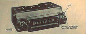
RADIO
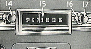
6 TUBE - MANUAL CONTROL TYPE
(17) RADIO ON AND OFF AND VOLUME KNOB
To turn the receiver on, turn the volume control knob (17) on the right hand side, until a click is heard and the dial (15) is illuminated. To increase the volume, continue to turn the knob to the right. To shut off the receiver, turn control knob to extreme left until a click is heard.
(16) RADIO TONE CONTROL KNOB
Tone control is regulated by the ring (16) behind the volume control knob. Turning this ring to right (clockwise) brings out the high notes, to the left (counter-clockwise) emphasizes the bass notes.
(14) RADIO MANUAL TUNING KNOB
After the receiver is turned on, turn knob (14) to the right or left to tune in stations manually for best reception.
(15) RADIO STATION DIAL
Indicates station frequency.
|
 |
 |
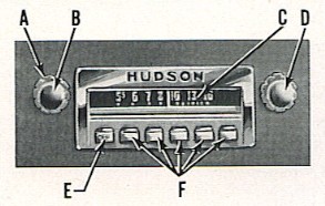
8 TUBE - PUSH BUTTON TYPE
RADIO ON AND OFF AND VOLUME KNOB
To turn the receiver on, press in any of the push buttons (F) except the one at the extreme left (E). This will automatically bring in the station for which the button has been set. To regulate the volume, turn volume control knob (B) closwise or counter-clockwise. To turn off the receiver, press in the button (E) at the extreme left.
(A) RADIO TONE CONTROL KNOB
Tone control is regulated by the ring (A) located behind the volume control knob. Turning this ring to right (clockwise) brings out the high notes, to the left (counter-clockwise) emphasizes the bass notes.
(D) RADIO MANUAL TUNING KNOB
After the receiver has been turned on by pressing in one of the five push buttons, it may be tuned manually to other stations by turning the manual tuning knob (D). This can be done at any time without disturbing the automatic setting.
AUTOMATIC TUNING
There are five automatic tuning positions, one for each of the five buttons (F) which may be adjsuted to the stations desired. If the positions have not been adjusted previously, details will be found in the Radio Owner Manual.
(C) RADIO STATION DIAL
Indicates station frequency.
|
 |
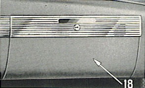
(18) LOCKER BOX AND LOCK
To lock, turn key one-quarter turn left. To unlock, turn key to vertical position and press in on lock.
|
 |
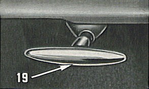
(19) PARKING BRAKE LEVER
To apply, depress brake pedal while pulling the parking brake lever handle straight back. To release, rotate handle 1/4 turn and push in. Be sure the parking brake lever is all the way in before starting the car.
|
 |
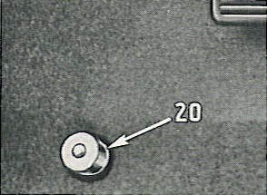
(20) HEADLIGHT DIMMER SWITCH
Located at upper side of floor panel, controls country (upper) beam and traffic (lower) beam. When meeting oncoming traffic and beam indicator on speedometer shows red, depressing dimmper switch once and releasing will change from country to traffic beam. Depressing and releasing dimmer switch the second time restores light beams to upper or country position.
|
 |
HUDSON WEATHER CONTROL
Click here for FULL explanation of weather control and servicing information.
|
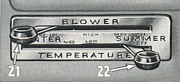
(21) WEATHER-CONTROL BLOWER LEVER
The upper or blower lever (21) operates the heater door, blower valve located inside the blower housing which directs air either to the passenger compartment when the car is driven at slow speeds or standing still or to the windshield for defrosting and the switch controlling the blower speed.
(22) WEATHER-CONTROL TEMPERATURE LEVER
The lower or temperature lever (22) operates a summer door located inside the heater housing for summer driving conditions and a thermostatic valve which automatically opens and closes to maintain the temperature selected for winter driving. Once set for the desired temperature the lever seldom needs adjustment. Move the lever to the left for the desired temperature.
|
 |
MORE CONTROLS
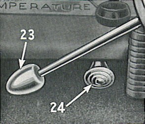
(23) DIRECTION INDICATOR LEVER
Pushing lever upward operates right hand turn signals (flashing lights in right tail lamp and right front parking lamps and right green arrow on speedometer dial). Pushing lever down flashes left turn signals. The lever automatically returns to the "OFF" (center) position when turn is completed.
(24) OVERDRIVE CONTROL KNOB
Push knob all the way in for operation of Overdrive. Also see "Overdrive Operation."
|
 |
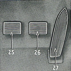
(25) CLUTCH PEDAL - MANUAL SHIFT TRANSMISSION
Clutch pedal should be depressed fully before starting he engine or shifting gears. Do not drive with the left foot resting on the clutch pedal as riding of the pedal causes clutch slippage and rapid clutch wear.
(26) BRAKE PEDAL
Depressing the brake pedal applies equal hydraulic force to all four wheels.
(27) ACCELERATOR PEDALControls car speed - also overdrive operation.
|
 |
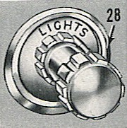
(28) LIGHTING SWITCH
Rotating the knob clockwise to the first position provides parking lights, instrument lights, tail lights and license light. Second position turns on headlights, tail lights, instrument lights and license light. Turning the knob the the extreme left turns off all lights.
|
REMOVAL
- Disconnect negative battery cable at baattery.
- Loosen set screw in control knob and remove knob.
- Using a suitable spanner, remove escutcheon nut and escutcheon.
- Remove switch and remove wires from switch.
INSTALLATION
Reverse procedure of removal.
|
 |
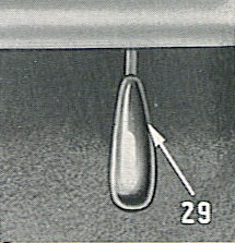
(29) COWL VENTILATOR HANDLE
Push handle forward to open cowl ventilator and pull back handle to close it. See "Weather-Control Operation."
|
 |
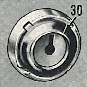
(30) IGNITION LOCK AND STARTER SWITCH
Insert key and turn right (against slight spring pressure) to engage starter. When engine starts, release key which will then return to the running position. Turn key to center position to turn off ignition or remove key. Turn key to left position for accessories and gauges.
|
REMOVAL
- Disconnect negative battery cable from battery.
- Remove Phillips head screw from underside of instrument panel.
- Remove switch and disconnect wires.
INSTALLATION
Reverse procedure of removal.
|
 |
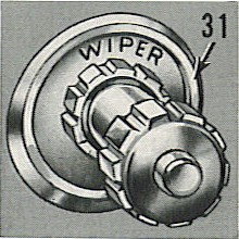
(31) WINDSHIELD WIPER CONTROL KNOB
Turning the knob to the right (clockwise) turns on and regulates the speed of wiper blades. Turning the knob to the left is "OFF." When car is equipped with a windshield washer, pressing the button in the center of the knob supplies solution for washing the windshield. [If looking to install a windshield washer, Winshield Washer Intallation Instructions are available.
|
REMOVAL
- Loosen screw attaching control wire to wiper motor and remove wire from motor.
- Loosen set screw in control knob and remove knob.
- Using a suitable spanner, remove excutcheon nut and excutcheon.
- Remove wiper control from panel and pull control wire through dash.
INSTALLATON
Reverse procedure of removal.
|
 |
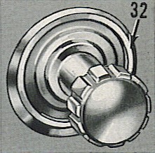
(32) CIGAR LIGHTER
Press in to operate. Automatically pushes out when the filament is hot. Do not hold in manually.
|
 |
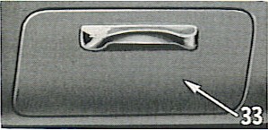
(33) ASH RECEIVER
Pull out drawer type. To remove, press down the snuffer and pull out complete ash receiver.
|
 |
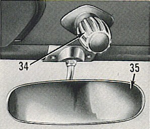
(34) RADIO ANTENNA OPERATING KNOB
To raise antenna, press in knob slightly and turn to right or left one-half turn. To extend antenna, turn knob one-quarter turn, pull out inner or telescopic section of antenna and turn knob until antenna is in upright position. Click here for printable Antenna Installation Instructions.
(35) REAR VIEW MIRROR
Inside rear view mirror can be adjusted by tilting.
|
 |
(36) DOME LIGHT
Lights automatically when rear doors are opened (Super Jet Models). Also operated by sliding switch on right door pillar.
|
 |
REMOVAL
- Disconnect the negative battery cable from the battery.
- With cars equipped with Weather Control, remove both control knobs from the heater control assembly and remove the fuse from the lead wire.
- Remove the two bolts attaching the hand brake support bracket to the instrument panel which also attaches the heater control assembly to the instrument panel and remove the one screw at the opposite side of control.
- Remove the heater control assembly and carefully place to one side - (leave all control cables attached).
- Remove the ignition switch assemby from the instrument panel, (leave all wires attached).
- Disconnect speedometer cable at speedometer.
- Using a six inch extension on a 1/4" ratchet set, remove the six 3/8" nuts from the studs attaching the instrument cluster assembly to the instrument panel.
- Pull the instrument cluster assembly forward sufficiently to expose the back face of the cluster assembly to allow removal of speedometer, fuel and temperature gauge and constant voltage regulator.
INSTALLATION
To install, reverse procedure of removal.
as suggested in Hudson Service Merchandiser Vol. 6, No. 1, January 1954
HORNET & WASP - 1954
Any one of the eight light bulbs may be replaced by reaching up behind the instrument panel.
To replace the speedometer, electric clock, fuel gauge, temperature gauge or voltage regulator, it is necessary to remove the instrument cluster. First, disconnent battery positive lead and disconnect speedometer. Remove eight 5/16" nuts from studs that hold the instrument cluster to dash. These are accessible without the necessity of removing radio.
Protect dash and shift control, leave all wires intact, laying instrument cluster backwith glass downward. Care must be exercised in the removal and installation of the speedometer, account of bending or damaging the indicator, to see that it lines up with the upper edge of rivet on speedometer face plate with approximately ½ inch clearance between the indicator and face plate.
When installing instrument cluster, tighten one stud, then check all lights and speedometer for operation.
To replace the instrument cluster glass, first remove as described above, then remove six metal screws which hold the glass retainer in position
JET - 1953 & 1954
The instrument cluster on the Jet for 1953 and 1954 may be laid back to make all instrument removal and installation accessible by first removing six nuts from ¼ inch studs. All instument light bulbs are removable from behind the instruments, and without removing the cluster, except the high beam indicator light bulb.
To remove this bulb, it is necessary to first unbolt and lay the instrument cluster back from the dash. Then remove the speedometer cover and two screws holding cover to speedometer.
In view of the inconvenience of replacing this bulb, be sure to use a Mazda 44 which is the longer life bulb.
The glass sections of any of the three instruments may be replaced by first removing the screws and retainers from the innder side - accessible only after laying the instument cluster back from the dash.
|
CONSTANT VOLTAGE REGULATOR
Follow same procedure as for "Fuel Gauge Removal" and "Installation."