Hudson Jet |  |
DISCLAIMER: Unless otherwise noted, service information has been provided by an edition of the Mechanical Procedures Manual and Hudson Owner Manual for Jet models. The data from the Manual includes information covering specifications, adjustments and detailed operation involved in maintenance and repair procedures. After market updates from Hudson Service Merchandisers and other sources have been added as well and are credited in italics. HudsonJet.net provides this reference as a courtesy and is not responsible for any work done using Hudson Motor Car Company's publications or other sources provided on this site. |
|
Protection
Temperature
10
0
-10
-20
-30 | Hudson
Anti-Freeze Qts.
4-¼
5-½
6-¾
7-¾
8-¾ | Methanol
Qts.
3-¼
4-¼
5-¼
6
6-¾ | Ethylene Glycol
Prestone or Equivalent) Qts.
4
5-¼
6-¼
7
7-¾ |
DESCRIPTION AND OPERATION
The cooling system is of the pressure type and has a cellular tubular radiator, a centrifugal six vane impeller pump and a 17" four blade radiator fan with the blades unevenly spaced to minimize noise.
The engine block contains a brass water distributing tube with holes properly spaced to direct the flow of water around the cylinders for efficient cooling.
By-pass thermostats are used to permit rapid engine warm up by restricting circulaton of the coolant through the radiator and by-passing it through the cylinder block until the coolant temperature rises sufficiently to open the thermostat. The temperatur range of the thermostats is as follows:
The standard thermostat starts to open at 150° to 155° and is fully open at 175°.
The high temperature thermostat starts to open at 165° to 170° and is fully open at 195°. (For use with Permanent Anti-Freeze.)
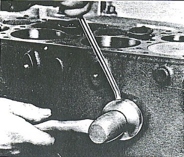
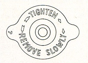
CAUTION: When removing pressrue cap while the engine is hot, always turn cap slowly counter clockwise until the stop is reached. Keep the cap in this position until all pressure is dissipated; then turn cap fully and remove.
To drain the cooling systen, open the radiator drain cock located at the lower right corner. Also remove the pipe plug in the cylinder block located at the rear left side. Remove the radiator cap to prevent air lock.
RUST AND SCALE DEPOSITS
Scale or rust tends to obstruct the flow coolant through the water passages of the cylinder block and radiator, when such formation is excessive, it prevents proper heat dissipation and results in overheating. This, in turn, causes loss in lubrication efficiency and accumulation of carbon, varnish and sludge.
If overheating exists due to clogging of the engine portion of the cooling system, the conditions should be ocrrected by the use of a reputable solvent or a reverse flushing.
CAUTION: Care must be used in the selection of cleaners as some of them contain strong acids or caustics that will react with the metal of the radiator core, eating holes through the metal and causing the radiator to leak.
Reverse flushing of the cooling system is the forcing of water through the radiator using air pressure and flushing in a dirction opposite to that of the normal flow of water.
The regular use of a cleaning and an inhibiting fluid in the cooling system and periodic reverse flushing will greatly reduce the formation of rust, scale and corrosion. The logical time for flushing and introductio of inhibitor is when the anti-freeze is installed in the fall and when it is removed in the spring.
A good inhibitor should be kept in the cooling system at all times. The effectiveness of any inhibitor is limited to about six months after which the cooling system should be flushed, refilled and new inhibitor added.
Hot water heaters should be flushed separately. Deposits build up in the heater core jsut the same as they do in the radiator core and will decrease the efficiency of the heater.
There are several anti-freeze solutions available that are satisfactory for automobile cooling systems. Among them are denatured alcohol, methanol (synthetic wood alcohol) and ethylene glycol. Do not mix different basic types of anti-freeze.
The alcohol type anti-freeze solutions are subjet to evaporation, especially on heaby runs, and should be tested frequently. Add as necessary to protect the cooling system for the lowest anticipated temperature.
CAUTION: These liquids, if spilled on the car, should be washed off immediately with a generous quantity of water to prevent damage to the finish.
If is advisable to tighten or replace all hose connections. It is important that the cylinder head be kept tight to prevent leakage.
If evaporation occurs with the use of ethylene glycol, it is only necessary to add water to the solution; however, the cooling ystem should be watched closely for leaks, and should be tested when additional water is required.
CAUTION: Solutions containing salt, calcium chloride, soda, sugar, or mineral oils such as kerosene or engine oil should never be used in the cooling system as they either clog the water passages or damage the hose connections and other parts.
The water pump features a permanently lubricated ball bearing for the pump shaft and a non-adjustable packing. A permanent seal, which makes repacking unnecessary, is sued to prevent leakage around the water pump shaft.
A large drain hole at bottom side of pump body allows for drainage and acts as a vent to minimize moisture formation in the pump assembly.
The pump shaft in mounted in a permanently lubricated double row ball bearing with grooves in the shaft to furnish raceway for the bearing balls and provide a means of taking end thrust of the fan and pump.
The bearing and shaft are retained in the pump housing by the shaft bearing retainer.
- Drain the cooling system
NOTE: It is not necessary to remove the radiator to remove the pump; however, use care when removing and installing the pump.
- Loosen the bolt in fan belt and generator adjusting bracket and move generator in toward the cylinder block to remove the fan belt.
- Disconnect hose from the water pump inlet.
- Remove the bolts and nut from the generator adjusting bracket to cylinder block and remove bracket.
- Remove the four bolts and lock washers attaching fan blades to fan pulley and hub, and remove the fan blades.
- Remove bolts attaching water pump to block and remove the water pump.
DISASSEMBLY
- Remove the water pump shaft retainer (7) and old gasket (13), Figure 1.
- Press out the pmp shaft and bearing assembly with water pump pulley hub attached using adapter plate between body and pulley hub.
The slotted adapter is placed between the body and the pulley hub to support the lower part of the body to eliminate spring-back and possible body fracture when removing the water pump shaft. The adapter (J-2778-3) is included in J-2778 Holding Fixture.
The bearing and shaft is serviced as an assembly only. The water pump pulley hub is not part of the shaft and must be removed from the old shaft and installed on the new shaft.
Figure 1
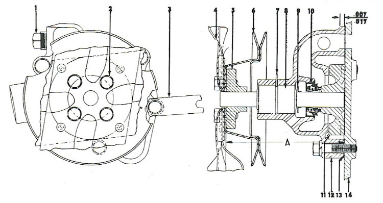
WATER PUMP - LEGEND |
- Body pipe plug
- Fan blade bolt and lockwasher
- Generator adjusting bracket
- Fan blade assembly
- Pulley hub
- Pulley assembly
- Bearing retainer
|
- Bearing and shaft assembly
- Shaft slinger
- Shaft seal
- Impeller
- Body
- Body to cylinder block gasket
- Cylinder block
|
WATER PUMP SHAFT, SEAL, AND BEARING INSPECTION
Clean the bore in the pump body and check for scores and wear.
Check the pump body at the area of the impeller and if the impeller has been scraping the body, itindicates improper clearance.
Check seal and if necessary replace seal. using a brass drift and working through hub bore of pump, drive out seal assembly.
Revolve bearing slowly by hand, using hand thrust load. If bearing does not drag or feel rough, it can be reused.
If steel seals at ends of bearing, outer races are loose so they can be turned with fingers, the bearing should be replaced.
Worn shafts and shafts with a worn spring retainer groove should be replaced.
ASSEMBLY
- Assemble the shaft and bearing in the water pump body.
NOTE: Bearing should be slight press fit into pump body, and assembled so that the groove on the outer race is aligned with the retainer wire slot in pump body bore.
CAUTION: When pressing bearing and shaft in housing, press against face of outer ring, not against shaft.
- Install seal assembly (10, Figure 1) as seal outer retainer is a press fit in pump body. Be sure seal is properly aligned. Use of a steel tube 1-5/8" outside diameter will facilitate assembly.
- Lubricate the shaft with engine oil and press on the fan pulley hub. Support the flange of the hub and apply pressure on the impeller end of the shaft. Maintain proper pulley spacing. This dimension should be 5-1/64" from the front face of pulley hub to rear end of shat (A-Figure 1).
- Instll impeller on shaft, be sure fron face of impeller is free of nicks and burrs. Support pump on fan end of shaft when installing impeller.
NOTE: Impeller and shaft must protrude .007" to .017" beyond cover face of pump body, Figure 1.
- Remove all traces of the old pump to block gasket and install new gasket and pump to engine. Be sure the proper gasket is used in roder to insure correct impeller to body clearance and install attaching bolts and tighten to 20 to 30 foot pounds.
- Install fan belt.
- Install pulley hub (5), fan blades (4), lock washers and screws (2). Tighten screws to 12 to 15 pounds to torque.
NOTE: Clearance from outside edge of fan blade to radiator cap should be 7/8"
- Install generator adjusting bracket.
- Install hoses.
- Install adjusting bracket bolt in generator bracket and adjust fan belt.
- Refill radiator.
|
FAN BELT ADJUSTMENT
[In original manual, however, italicized portion is an additional excerpt as suggested in Hudson Service Merchandiser Vol. 5, No. 4, April 1953.]
The fan belt is of the "V" type and drives the water pump and generator through the vibration dampener pulley.
The belt is adjustable by means of a swinging generator mounting. Moving the generator away from the engine increases the belt tension, while moving it towards the engine decreases its tension. Belt adjustment is correct when it is possible to depress the belt approximately 3/8" to 1/2".
Due to the design, it is desirable to adjust the fan belt tension on the [Jet] Engines with a torque wrench. Although there is outlined in the Owner's Manual for these cars a procedure that will enable an owner to adjust the belt, for long life and minimum wear on water pump bearings, the following procedure is recommended.
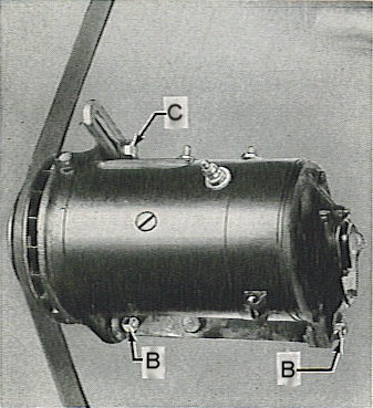
- Loosen generator adjusting bracket bolt (A, Figure 2), nut (B) and 2 generator support bracket bolts (D) three to four turns.
- Apply a torque wrench approximately 12" long and as nearly vertical as possible to the head of generator adjusting bracket bolt (C) and pull generator against fan belt.
- With torque wrench indicating 10-1/2 ft. lbs. tighten generator adjusting nut (B) securely. Remove torque wrench and tighten remaining 3 bolts securely.
|
Figure 2
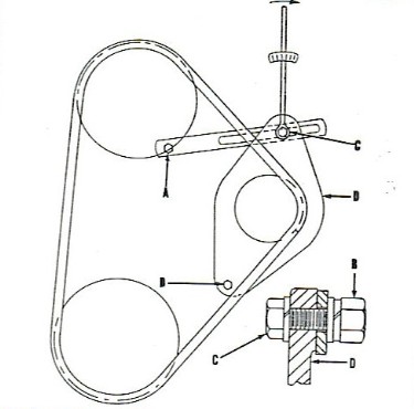 |
Figure 2B
|
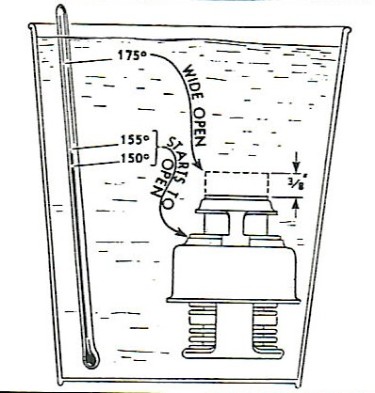
The temperature at which the thermostat opens is very important and it should be checked whenever the complete cooling system is being checked.
CAUTION: In cases of extreme overheating or freezing, check the thermostat, as excessive temperature may have caused the bellows to take a set i the expanded position.
Place the thermostat in a pail of water with a thermometer and heat the water until the thermostat starts to open. The thermometer should show from 150° to 155° F, Figure 3. Continue heating the water until the thermostat is wide open. The thermometer should show 175° F.
Discard thermostats that:
Do not open completely.
Open at too low a temperature.
Open at too high a temperature.
A thermostat that opens too soon will cause the engine to operate at too low a temperature and if it opens too late or is sticking, it may cause the engine to overheat.
|
Figure 3
 |
NOTE: High temperature thermostats are also available, these start to open at 165° to 170° F. These should be used with permanent type Anti-Freeze to insure maximum heater efficiency.
|
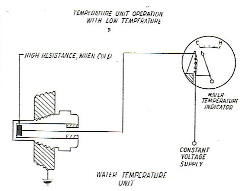
WATER TEMPERATURE GAUGE
When the coolant is cold, the highest resistance in the unit causes the instrument panel gauge to read at the cole end of teh dail with ignition switch turned on, Figure 4.
|
Figure 4
|
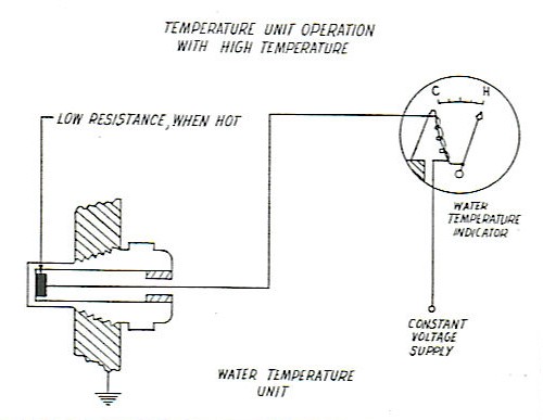
When the coolant is hot, the low resistance in the unit causes the instrument panel gauge to read at the hot side of the dial with ignition switch on, Figure 5.
|
Figure 5
|
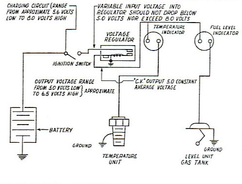
VOLTAGE REGULATOR
The constant voltage regulator is common to both the temperature and fuel systems, that is, one regulator is sued to operate both systems, Figure 6.
METHOD OF CHECKING
- If both gauges read too high - for example, if the temperature gauge reads up scale with a cold engine, and the gas gauge reads up scale with an empty gas tank - the constant voltage regulator is not working properly and should be replaced. (Check ground connections of the voltage regulator as grounding is essential to the proper fuctioning of the regulator).
- If both gauges read too low, either the input voltage to the C.V. regulator is below 5.0 volts or the voltage regulator is inoperative and should be replaced. Check battery voltage output before replacing regulator.
- To check cylinder block sender unit proceed as follows:
- Submerge unit in water up to the hexagon shoulder.
- Attach "Ohm" meter to terminal.
- With water temperature at 160F°:, resistance must be 25.8-30.8 Ohms.
NOTE: It is not advisable to attempt any repairs or adjustments to either unit of the gauge since they are factory calibrated and attempt to repair is impractical. |
Figure 6
|
The water jacket plugs used in the left side of the cylinder block are a drive fit and can be easily installed using tool J-2793 as illustrated in Figure 7. use a light coat of Hudson Perfect Seal Paste to facilitate installation and improve the sealing. The plug is started into place and then driven into the block with the installer until the shoulder of the installer contacts the block. Figure 7.
|
Figure 7
|
RADIATOR PRESSURE CAPAll models are equipped with a pressure type radiator filler cap which is designed to maintain a slight pressrue in the cooling system. This cap should be in place and always turned down tightly to maintain correct pressure.
CAUTION: When removing the filler cap while the engine is hot, place a piece of cloth over the cap and turn the cap 1/4 turn counter-clockwise until the stop is reached. Keep the cap in this position until all pressure is released, then turn the cap fully to the left (counter-clockwise) and remove.
|
 |
DRAINING
To drain the radiator, raise the hood, turn the handle of the drain clock located at the lower right rear corner of the radiator, counter-clockwise. To completely drain the cooling system, also remove the pipe plug located at the left rear corner of the cylinder block.
NOTE: If it is necessary to save the coolant when draining, place a piece of hose over the drain cock and the losoe end of the hose in a container.
FILLING
Proper care of the cooling system is highly essential to maintain efficient engine operation. Rust and scale in the cylinder block is a natural product of water and iron. When filling the cooling system, use clean water and Hudson Rust and Corrosion Inhibitor. Never pour cold water or anti-freeze into the radiator when the engine is overheated. Always allow engine to cool to normal operating temperature.
In the fall before adding anti-freeze and in the spring after draining, the use of Hudson Rust and Corrosion Inhibitor (omit if anti-freeze contains an Inhibitor) will assist in a great measure to prevent corrosion and scale which tend to clog the passages. The cooling system capacity is 15 quarts. Cars equipped with Weather-Control require one additional quart. Maintain coolant level 1-1/2" below top of filler neck, measured when hot.
ANTI-FREEZE
Always drain and flush the cooling system to insure unrestricted circulation before installing anti-freeze. Also carefully check all hoses and gaskets for leaks or signs of deterioration.
Do not use anti-freeze solution containing calcium, salt, or other ingredients which promote electrolytic action. Glucose and honey clog the radiator; kerosene and fuel oil when hot, expel inflammable vapors. DO NOT mix permanent and alcohol base anti-freeze solution. Hudson Approved Anti-Freeze [was] available in both types.
Have the coolant solution tested frequently to avoid a freeze-up. In climates where anti-freeze solutions are not required, flush the cooling system at least twice a year and add Hudson Rust and Corrosion Inhibitor every time the cooling system is drained and refilled.
Protection
Temperature
+10
0
-10
-20
-30 |
Hudson
Anti-Freeze Qts.
4-1/4
5-1/2
6-3/4
7-3/4
8-3/4 |
Methanol
Qts.
3-1/4
4-1/4
5-1/4
6
6-3/4 | Ethylene Glycol
(Prestone or Equivalent) Qts.
4
5-1/4
6-1/4
7
7-3/4 |
REMOVAL
- Drain radiator and disconnect hoses.
- Remove two sheet metal screws attaching deflector shield to fender tie panel.
- Disengage headlamp wireing from retaining clips at front of radiator.
- Remove the four hexagon bolts attaching the radiator to "U" channel and remove radiator.
INSTALLATION
Reverse procedure of removal.
NOTE: Proper clearance between the fan blades and radiator core is 7/8".
Should the fan be too close, there is danger of damaging the radiator on an emergency stop. If set too far from the core, cooling efficiency will be impaired particularly at low speed.
Provision for adjusting the positions of the radiator core is by means of elongated holes at each side of the radiator mounting channel. A cap screw and a lip in each bracket fits in the elongated holes and limits the amount of adjustment.
EXCESSIVE ENGINE TEMPERATURE CAUSES
- Ignition timing too late or too early.
- Fan belt slipping.
- Radiator or cylinder block clogged or restricted.
- Radiator core outside surface covered by grille covers, ornaments, etc.
- Outward air passages clogged with bugs or dirt accumulations.
- Thermostat defective.
- Collapsed water pump inlet hose.
- Pump inpeller loose on shaft or improper clearance of impeller in pump housing.
- Engine fan blades not set at proper pitch.
- High engine friction resulting from:
- Insufficient internal clearance
- Internal misalignment
- Use of heavy engine oil
- Inadequate oil circulation
- Dragging brakes or tight wheel bearing.
- use of certain types of anti-freeze solutions in warm weather.
- Slipping clutch.
Water Pump: Thompson # FP1154, SealedPower #PC129, McQuay/Norris # PE121, Grapo/NAPA # CP302
Thermostat: Visit RockAuto.com for a couple different thermostat options.
|
|
|
|
Courtesy HET JetSet - All Rights Reserved.
|
|