Hudson Jet


DISCLAIMER: Unless otherwise noted, information has been provided by an edition of the Hudson Owner Manual for Jet models. The Owner's Manual was specifically prepared to give the driver suggestions and information, helpful hints and ideas that would assist in enjoyment of the vehicle and ensuring lowest upkeep and operating costs. After market updates from other sources have been added as well and are credited in italics. HudsonJet.net provides this reference as a courtesy and is not responsible for any work done using Hudson Motor Car Company's publications or other sources provided on this site.

WEATHER CONTROL

Return to Servicing Index
You should know all about the instruments and operation of the controls before driving your car. So that you will be able to interpret each instrument reading and the proper function of each control, [it is] recommended that you read the following instructions carefully before driving your car.
Hudson Weather-Control has been designed for maximum passenger comfort and simplicity of operation. The Hudson Weather Control as used on Hudson Jet Models is a fresh air ventilating and heating unit being so constructed as to provide summer ventilation, winter heating and windshield defrosting with simplicity of control.

The cowl ventilator remains open for all heating, ventilating and defrosting conditions except for a short period of engine warm-up during cold weather. The cowl duct is fitted with a trap to prevent water entering the car through the open cowl ventilator.

All the air supplied by the Hudson Weather Control is fresh outside air, warmed and reduced in relative humidity. This "dryer" air reduces fogging and frosting of the windshield and windows.

The entire operation of the weather-control unit is accomplished by two levers, located on the left side of the instrument panel, the upper or blower lever (21) and the lower or temperature lever (22).

(21) WEATHER-CONTROL BLOWER LEVER
The upper or blower lever (21) operates the heater door, blower valve located inside the blower housing which directs air either to the passenger compartment when the car is driven at slow speeds or standing still or to the windshield for defrosting and the switch controlling the blower speed.

(22) WEATHER-CONTROL TEMPERATURE LEVER
The lower or temperature lever (22) operates a summer door located inside the heater housing for summer driving conditions and a thermostatic valve which automatically opens and closes to maintain the temperature selected for winter driving. Once set for the desired temperature the lever seldom needs adjustment. Move the lever to the left for the desired temperature.

Weather-Control Blower Lever
COLD WEATHER DRIVING
Open the cowl ventilator as soon as the temperature gauge hand begins to move to the right.

Move the lower temperature lever (22) to the desired setting, either low, medium or high.

If the car is being driven at slow or interrupted traffic speeds in cold weather and additional heated air circulation is desired the upper or blower lever (21) may be moved to the low or high position. This action closes the heater door and turns on the blower to increase the flow of heated air to the passenger compartment through the blower outlet.

Further movement of the blower lever to the "Defog" position partially closes a damper valve in the blower outlet forcing a portion of the heated air up through the defroster tubes to the windshield and also allows some of the heated air to enter the passenger compartment.

Full movement of the lever to the "De-Ice" position completely closes the damper valve in the blower outlet forcing all of the heated air through the defroster tubes to the windshield to remove snow or ice. When starting out with a cold car, and particulary with a full pasenger load, some fogging or frosting may develop. This can be reduce by turning on the defroster fan which is controlled by the switch knob on the front of the heater. The fan should be turned off after the windows are clear of frost or fog.

The defroster fan should also be turned on when icing of the windshield occures and while standing or at low speeds (either summier or winter driving) when the forward movement of the car is not sufficient to supply the required air flow through the cowl ventilator. The cowl ventilator must be open when the defroster fan is being used.

When driving at high speeds in extremely cold weather, it may be more satisfactory to cut down the air flow by PARTIALLY closing the cowl ventilator. This will give an increase in the temperature of the air delivered by the heater.

Heat is distributed from the front, back and both sides of the heater case so that a large volume of air can be supplied to adequately heat or coll the entire car interior without an excessive amount of air being directed on any of the front seat passengers. A knob located on the left side of the heater case controls the amount of air directed on the driver's feet. The maximum is obtained when the knob is in the up position.

NOTE: To obtain maximum efficiency of your Hudson Weather Control during cold weather driving, the following rules should be observed:
  1. The cowl ventilator should be kept fully open after the engine warm-up period except when driving at high speeds in extremely cold weather when partial closing of the ventilator will increase the temperature of the air entering the car. Water or snow entering the cowl ventilator while driving is trapped and drained off.
  2. Ventilating wings and windows should be fully closed except possibly when using the heater for defrosting when itnerior temperatures might become higher than desired. Open windows or ventilator wings cause loss of heat and prevent normal circulation of air and heating in the passenger compartment.
WARM WEATHER DRIVING
For warm weather driving the cowl ventilator should be fully open with the lower or air temperature lever in the Summer Open position. With the lever in this position the summer ventilating door located inside the heater housing is opened to allow the majority of fresh air to bypass the heater core which results in a greater volume of fresh air entering the passenger compartment. With the lever in this position the thermostatic valve is turned off.

At low speeds (normal driving) windows and ventilator wings can be open as desired for additional air circulation or the upper lor blower lever may be moved to the high position, which operates the blower motor and will increase the amount of fresh air entering the car.

At high speeds close windows and ventilator wings for minimum wind noise and wind burn. Opening the rear quarter wings slightly on Super Jet Sedan models will help maintain full air flow throughout the passenger compartment.

When driving on dusty roads keep the cowl ventilator fully open and keep all windows and ventilator wings closed. This maintains a slight air pressure in the passenger compartment and prevents dust from entering.

WEATHER CONTROL ASSEMBLY REMOVAL
  1. Remove both heater control knobs from heater control assembly.
  2. Remove the fuse from the lead wire.
  3. Remove the two bolts attaching the hand brake bracket to the instrument panel which also attaches the heater control assembly and one screw at the opposite side of the control assembly.
  4. Remove the sheet metal screws and clamps and disconnect all Bowden wires and remove the assembly.
NOTE: It is advisable to perform operations (1)-(2) and (3) when replacing Weather Control Blower Switch.

INSTALLATION
Reverse procedure of removal.

WEATHER CONTROL WATER VALVE
1D, 2D, & 3D
as suggested in Hudson Service Merchandiser Vol. 6, No. 3, March 1954

Beginning with car No. D-2292652, a change was made in the weather control water valve in that the capillary tube which heretofore was secured to the heater core is now coiled at the side of the water valve. Note illustration below.

The part number of the new water control valve is 311043. It is interchangeable with the former type.

Weather Control Water Valve
REPLACEMENT PARTS
Part No.

Name

Per Car
Replace with...

HA 308856

BO 161447
BO 308859
Weather-control complete

Seal-upper-water tube to dash
Seal-lower-water tube to dash
1

1
1


BO 171369
BO 170965
BZ   70874

Bolt & L/Washer assembly-w/c to air duct
P/Washer-w/c to air duct bolt
Nut-w/c to air duct bolt

4
4
1


BO 308861
BO 308864
BO 308862
BO 159079

Pipe assembly-w/c to water pump
Hose-cylinder head to Ranco Valve
Hose-valve to heater
Hose-72" long-1/2" I.D. (Service)

1
1
1


BO 171586
BO 303895
BO 171665
BO 308860

Connector-w/c to water pump pipe
Nipple-at cylinder head
Clamp-hose
Clip-w/c to water pump pipe

1
1
6
1


BO 308847

Wire assembly-w/c switch to ignition

1


BO 308858

Fitting-w/c installation bag of

1


BO 306788
BO 171816
BO 301887
BO 301888
BO 302054
BO 170617
BO 301889
BO 170304

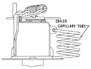
Valve assembly-weather control water (Ranco)
Screw-valve to dash
Seal-valve dash hole
Plate-valve dash hole seal
Screw-valve dash hold plate
Clip-w/control capillary tube
Screw-capillary tube clip

1
2
1
1
1
1-2
1
1


C   308854
C   308850
C   308851
C   308852
C   308853
BO 308403
BO 171889
BO 171894

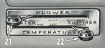
Control assembly-weather control (Instrument pul)
 Bowden wire-heater outlet control (40-1/2")
 Bowden wire-temperature control (46-1/2")
 Bowden wire-defroster control (38-1/2")
 Bowden wire-vent door control (46-1/2")
Knob-control lever
Screw-control lever knob
Bolt-RH-control to instrument panel

Control atached on LH by handbrake to instrument panel bolt

1
1
1
1
1
2
2
1


BO   12481
BO   71153
BZ  171155
BO 305817

Nut-control to instrument panel bolt
L/Washer-control to insturment panel bolt
P/Washer-control to instrument panel bolt
Clip-bowden wire to dash

1
1
2
1


BO 236672
BO 170941

Escutscheon-control
Screw-control escutcheon attaching

1
4


BO 309147
BO 171605
BO 308404
BO 308405

Nozzle assembly-defroster outlet
Screw-defroster outlet retaining
Hose-defroster (11")
Hose-defroster (25")

2
2
1
1


Courtesy HET JetSet - All Rights Reserved.