HudsonJet.net |  |
DISCLAIMER: Unless otherwise noted, service information has been provided by an edition of the Mechanical Procedures Manual, Body Manual, and the Hudson Owner Manual for Jet models. The data from the Manuals includes information covering specifications, adjustments and detailed operation involved in maintenance and repair procedures. After market updates from Hudson Service Merchandisers and other sources have been added as well and are credited in italics. HudsonJet.net provides this reference as a courtesy and is not responsible for any work done using Hudson Motor Car Company's publications or other sources provided on this site. |
|
BODY - FRONT END / REAR COMPARTMENT |
ENGINE HOOD
REMOVAL
- Raise the hood assembly.
NOTE: Mark the original position of the hood hinges before removing hood assembly to facilitate installation.
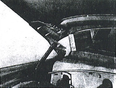
- Remove the bolts (A), Figure 102, (two each side) attaching the hood to the hood hinges and with the assistance of a helper, remove hood from the car.
INSTALLATION
Reverse procedure of removal and adjust as necessary. |
FIGURE 102
 |
HOOD ADJUSTMENT
- Loosen bolts (A), Figure 102, (two each side) attaching the hood to the hood hinge; this will allow forward and backward adjustment.
- The up and down adjustment at the rear of teh hood can be obtained by loosening the bolts (B) attaching hood hinge to the fender assembly. Loosen the bolts about 1/2 turn. Move hinge up or down a small amount each time until desired position is obtained. Tighten bolts securely each time before lowering hood.
- The up and down adjustment at the front of the hood can be amde by loosening the hood lock plunger nut at (A), Figure 103, and with a screw driver turn lock plunger (B) clockwise to decrease and counter-clockwise to increase. After adjustments are made, tighten plunger lock nut securely.
|
FIGURE 103
 |
HOOD LOCK - UPPER
REMOVAL
- Remove the three bolts (C), Figure 103, attaching hood lock to hood support and move hood lock.
INSTALLATION
Reverse procedure of removal and adjust as necessary.
HOOD LOCK - LOWER
REMOVAL
- Remove the four bolts (A), Figure 104, attaching lower hood lock to lower hood support and remove the lock.
INSTALLATION
Reverse procedure of removal. |
FIGURE 104
 |
HOOD HINGE
REMOVAL
- Raise the hood, place a block of wood between hood and cowl panel to support the hood when the hood hinge bolts are removed, Figure 105. It is advisable to mark the original positino of the hood hinge before removing to facilitate the installation of the new hinge.
- Remove the two bolts attaching the hood hinge to the fender and the two bolts of the hood and remove the hood hinge assembly.
INSTALLATION
Reverse procedure of removal and check hood adjustment.
|
FIGURE 105
 |
|
FRONT FENDER
REMOVAL
- Raise the hood and disconnect the headlamp wires at junction block (located on radiator support channel).
- Remove headlamp ring (one Phillips head screw).
- Remove the four screws attaching headlamp assembly and remove headlamp and "Sealed Beam" unit. (See "Head Lamps" under the Electrical section if further detail is needed.)
- From underneath the fender remove two nuts and washers attaching grille upper moulding to fender and the three screws attaching the upper grille moulding to the grille structure.
- Remove five screws (Phillips) attaching the parking lamp ornament to the upper and lower grille louvers.
- From underneath the front fender remove the three bolts and nuts attaching the fender to grille structure and snap out parking lamp socket and bulb assembly.
- Place a block of wood between rear of hood and cowl panel to support hood, see Figure 105, and remove the two screws attaching hood hinge support to hood.
- Remove the five self tapping screws attaching the fender to the fender side shield.
- From inside of car, carefully snap out kick pad at the side of dash panel and remove the three botls attaching the front fender to the fron tpillar assembly and the one bolt to cowl panel.
- At the rear underside of front fender, remove the two bolts attaching fender to body and remove fender.
INSTALLATION
- With the aid of an assistant, align fender at cowl panel and attach screws at door hinge pillar opening.
- Attach fender to side dust shield and grille structure.
- Reverse procedure of removal on balance of installation.
NOTE: Reseal fender at cowl panel and focus headlights.
FRONT FENDER STONE GUARD and PANEL ASSEMBLY
REMOVAL
- Remove four bolts attaching stone guard and panel to front quarter dash panel under the fender, two bolts under rubber pad, and one located to the left of hood hinge.
- Remove three Phillips head scres and spped nuts at dush shield extension rubber shield.
- Remove the panel and stone guard.
INSTALLATION
Reverse procedure of removal.
|
RADIATOR GRILLE |
REMOVAL
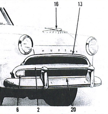
- The upper grille moulding (13), Figure A, can be replaced without removing any other part of the grille.
- From underneath the front fenders, remove two nuts (each side) attaching the upper grille moulding to the fenders.
- Raise the hood and remove the sex Hexagon sheet metal screws attaching grille moulding to grille structure and remove the upper grille moulding.
INSTALLATION
To install, reverse procedure of removal, attaching all screws before tightening to facilitate installation.
|
FIGURE A
 |
REMOVAL
- From underneath front fender (either right or left side) remove the two nuts attaching upper grille moulding to front fender.
- Raise the hood and remove three of the hexagon head sheet metal screws attaching the upper grille moulding to grille structure.
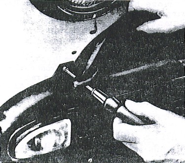
- Pull upper grille moulding out approximately 2" (Do not bend) and remove the one screw that is hidden behind the upper grille moulding, Figure B. (This screw attaches the parking light ornament assembly to the front fender.)
- Remove the five small sheet metal screws attaching the parking light ornament assembly to the upper and lower grille louvers.
- From underneath the front fender, remove the three nuts attaching the parking light ornament assembly to the fron tfender and te one nut attaching the ornament tab to the fender.
- Snap out bulb and remove the parking light and ornament assembly.
- From the opposite side remove the two small sheet metal screws attaching upper grille louver to the parking light ornament assembly.
- Remove the four hexagon head sheet metal screws attaching upper grille louver to center of grille structure and remove the upper grille louver.
|
FIGURE B
 |
INSTALLATION
Reverse procedure of removal.
NOTE: Install the four hexagon head sheet metal screws attaching upper grille louver to grille structure first, but do not tighten until all the other screws have been installed.
REMOVAL
- Perform operations (1), (2), (3), (4), (5) and (6) under "Grille Upper Louver Removal" and from the opposite side, remove the three small sheet metal screws attaching the lower grille louver to the parking light ornament assembly.
- Remove the nine sheet metal screws attaching the lower grille louver to the lower baffle of the grille structure and remove the lower grille louver.
INSTALLATION
Reverse procedure of removal, installing all screws before tightening.
REMOVAL
- Remove the upper grille moulding.
- Remove either parking light and ornament assembly.
- Remove upper and lower grille louvers.
- Remove the seven screws attaching the lower hood lock mounting plate to the upper section of grille structure and remove the lock plate.
- Remove the three bolts and nuts on each side attaching the grille structure to the front fenders.
- Remove the four sheet metal screws on each side attaching the grille structure to the radiator mounting channel.
- From either side, slightly pry out the grille structure assembly from under the lip of the front fender and remove the grille structure assembly.
INSTALLATION
To install, reverse procedure of removal. Install all bolts and screws before tightening to ensure proper grille strcture alignment.
REMOVAL
- From underneath front fender, remove the two nuts attaching upper grille moulding to front fender.
- Raise the hood and remove three of the hexagon head sheet metal screws attaching upper grille moulding to grille structure.
- Pull upper grille moulding out approximately 2" (Do Not Bend) and remove the one screw hidden behind the upper girlle mouldign attaching the parking light ornament to the front fender. See Figure B.
- Remove the five small sheet metal screws attaching the parking light ornament assembly to the upper and lower grillee louvers.
- From underneath the front fender, remove the three nuts attaching the parking light ornament to the front fender and the one nut attaching the ornament tab to fender.
- Snap out bulb and remove the parking lamp and ornament assembly.
NOTE: To remove the parking light lens, remove two nuts attaching parking light socket body and the three screws attaching parking light lens.
INSTALLATION
To install, reverse procedure of removal.
REMOVAL
- Drain cooling system and remove radiator hoses.
- Remove the two screws attaching the wire connectors at each side of radiator mounting channel (leave wires attached).
- Remove the hood lock support with lower hook lock attached.
- Remove the two sheet metal screws attaching radiator mounting channel to upper section of grille structure and three sheet metal screws on each side between upper and lower grille louvers.
- From under each front fender, remove two hexagon head sheet metal screws attaching fender dust shields to the radiator mounting channel.
- Remove the bolt attaching the radiator mounting channel to the front frame bracket and remove radiator mounting channel and radiator core as an assembly.
INSTALLATION
To install, reverse procedure of removal.
|
|
REMOVAL
- Raise compartment door.
- Remove the bolts on each side attaching the comaprtment door to the hinge upper bracket.
- With the aid of a helper, remove compartment door.
- If the original compartment door is to be installed, it is advisable to mark the position of the hinges on the compartment door to facilitate installation.
INSTALLATION
Reverse procedure of removal.
ADJUSTMENT
- Adjustment is accomplished by loosening the upper support hinge bolts, this will allow the compartment door to be shifted forward or toward the rear or side to side.
- Loosening the body hinge support bolts will allow the compartment door to be raised or lowered.
- Adjust compartment door lock striker if necessary.
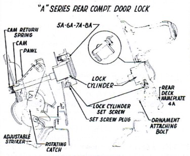
REMOVAL
- Raise compartment door.
- Through opening between compartment door and compartment door reinforcement remove lock cylinder housing retainer (spring clip).
- Remove lock cylinder assembly.
INSTALLATION
To install, reverse procedure of removal.
REMOVAL
- Remove compartment door lock cylinder. (See "Compartment Door Lock Cylinder Removal").
- Remove two screws attaching comaprtment door lcok cover to compartment door.
- Remove one bolt attaching lock to compartment door reinforcement and remove lock.
INSTALLATION
To install, reverse procedure of removal and check door lock striker adjustment.
|
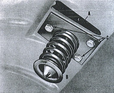
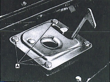
ADJUSTMENT
- The rear compartment door should lock by slight hand pressure.
- To adjust, loosen the two screws, then raise or lower the striker in the elongated holes. Raising the striker upward causes the door to close with less pressure and lowering the striker causes the door to close more tightly.
- Tighten both screws securely after making adjustment.
NOTE: The striker is positioned properly when the top of the striker is 3/32" above the top of the channel on the rear compartment panel, Figure 111.
|
FIGURE 111
 |
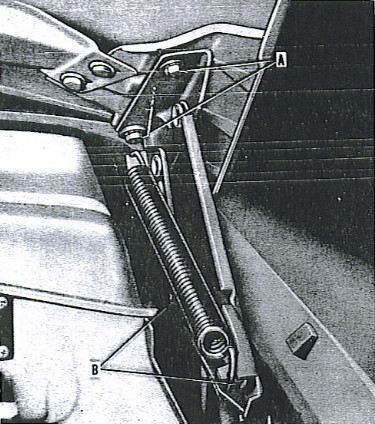
REMOVAL
- Raise compartment door.
- Mark original position at both attaching places before removing hinge to facilitate installation.
- Place a block of wood between compartment door and rear roof panel to hold compartment door in position.
- Remove the attaching bolts from upper hinge bracket to compartment door and the bolts attaching the lower hinge bracket to body reinforcement.
- Remove the hinge assembly.
INSTALLATION
To install, reverse procedure of removal and check adjustment.
INSTALLATION
- Prior to installation, make sure all surfaces to be cemented are clean.
- With a brush, coat both the cementing surface of the rubber weatherstrip and the corresponding surface with a light coat of weatherstrip adhesive.
- Position weatherstrip, and working across the bottom and up each side, press the weatherstrip firmly into position.
NOTE: Allow sufficient time for drying before closing compartment door.
|
|
FRAME AND BODY ALIGNMENT - All Hudson Models 1948 through 1954
FRAME ALIGNMENT
The frames of all Hudson models 1948 thru 1954 are similar in design although there are differences in dimensions due to wheelbases and changes in other details.
To check the frame for any misalignment, determine the model and refer to the correct frame dimension illustration [in 1948-1954 Hudson Body Service Manual]. The various dimensions shown may be used as a guide in checking alignment and covers only the more important diagonal measurements that should be checked; however, many more diagonal measurements may be made in the same manner.
Diagonal measurements should be taken when straightening the frame, and the measurements from similar points on the right and left side should be equal. These measurements make an excellent cehck for any out-of-square condition and misalignment and will quickly determine which section of the frame is bent and where pressure should be applied to restore correct alignment.
One method of checking is by use of tram gauges. When using tram gauges, keep the cross bar level to insure accuracy when making all measurements.
Another method is by using a "plumb bob". To insure accuracy, the car should be on a level floor and the points measured should be transferred accurately from the frame to the floor, then the distances between chalk marks on the floor may be easily measured.
After the frame has been straightened, the side rails and members should be closely inspected. If cracks appear these members should be reinforced or replaced.
If it is necessary to weld-in a new frame section, localize the heat in order to retain the original steel hardness. All welding should be done with arc welding equipment.
Questions welcomed...
Answers coming soon...
|
|
|
|
Courtesy HET JetSet - All Rights Reserved.
|
|