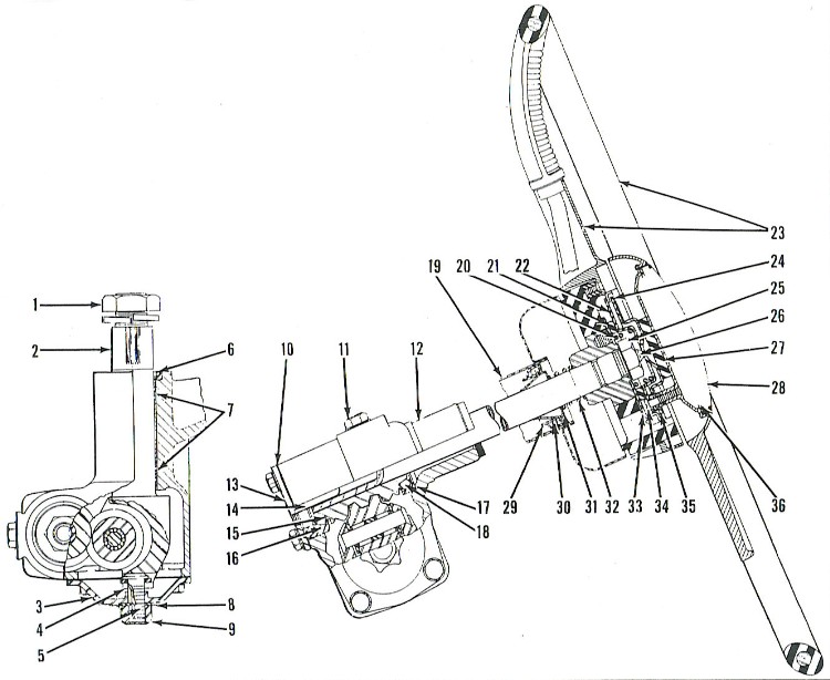
FIGURE 1
 |
| LEGEND |
- Gear shaft nut
- Gear shaft
- Gear shaft cover
- Adjusting screw thrust plate
- Adjusting screw
- Oil seal
- Bushings
- Adjusting screw lock plate
- Adjusting screw lock nut
- Worm cover shims
- Oil filler plug
- Housing
- Worm shaft cover
- Grease retainer tube
- Worm shaft lower bearing
- Worm shaft lower bearing cup
- Worm shaft upper bearing cup
- Worm shaft upper bearing
|
- Steering jacket tube assembly
- Index plate spring
- Index plate shock pad
- Index plate
- Steering wheel assembly
- Horn button contact cup
- Steering wheel nut
- Horn wire assembly
- Pressure contact pad
- Horn button and horn ring
- Jacket tube bearing retaining spring
- Jacket tube bearing assembly
- Jacket tube bearing spacer
- Jacket tube bearing spring
- Horn ring blowing cam
- Horn ring screw
- Insulator step washer
- Steering wheel horn button spacer
|
|
|
Type
Ratio
Gear Shaft Bearings
Worm Shaft Bearings
High Point
Turning Radius Right
Turning Radius Left
Lubrication
Wheel Nut Torque
Gear Shaft Nut Torque
Gear to Frame Bolts |
Worm and 2 Tooth Roller
18.2 to 1
Bronze Bushings
Tapered Roller
Notch on Steering Column Straight Down
16' 8-1/2"
16' 8-1/2"
S.A.E. 90 E.P. Gear Oil
20 to 30 foot pounds
125 to 140 foot pounds
50 to 60 foot pounds |
|
The steering gear employs a worm gear and two tooth roller gear shaft.
The worm is pressed on the lower end of the steering column tube and operates on two adjustable taperd roller bearings. The two tooth roller operates on needle bearings. The gear shaft operates in bronze bushings pressed into the housing.
a leather seal at the end of the gear shaft protects the unit against loss of lubricant. A grease retainer tube is pressed into the worm cover to provide a passage for the horn wire and seal the lubricant in the housing.
A thrust plate is assembled on the end of the gear shaft adjustment screw and fits into a slot in the end of the gear shaft. The adjustment screw is held in place by a lock plate and lock nut. Adjustment of the roller shaft for proper mesh with the worm gear is accomplished by turning the adjustment screw in the gear shaft cover.
Adjustment of the worm gear for end play is accomplished by removing or inserting shims between the worm cover and housing.
The steering gear is filled at the factory with S.A.E. 90 E.P. lubricant, which is satisfactory for all seasons. The steering gear filler plug should be removed and lubricant checked at each 1,000 miles lubrication period.
REMOVAL
- Disconnect horn wire at horn relay.
- Push down on horn button (28), Figure 1, rotate to release, and remove button.
- Remove horn wire assembly.
- Remove steering wheel nut and pull off steering wheel using puller J-3044.
INSTALLATION
- With notch in main column tube straight down, place steering wheel in position on tube with spokes straight across
- Install steering wheel nut and tighten to 20 to 30 foot pounds.
- Insert horn wire into steering column tube and apply a little grease on head of terminal.
- Install horn button and rotate to lock in place.
|
REMOVAL
- Remove steering wheel.
- Remove jacket bearing spring and spacer.
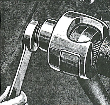
- Engage fingers of bearing puller J-2792 below the bearing and place locating pins in slots in head of puller, Figure2.
- Turn the center screw of puller against steering column tube and remove bearing.
|
FIGURE 2
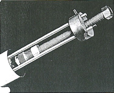 |
INSTALLATION
- Start bearing into jacket tube by hand.
- Using replacer tool J-2952, figure 3, drive bearing to a depth of 7/32" from top of tube, with or without directional indicator.
- Replace jacket bearing spacer and spring.
- Replace steering wheel.
|
FIGURE 3
 |
REMOVAL
- Remove steering wheel.
- Remove bearing spring and spacer.
- On car equipped with directional indicator, remove switch assembly.
- Remove steering column bracket cap at instrument panel.
- Loosen remote control tube bracket (lower) and jacket tube clamp at steering gear, and remove jacket tube.
INSTALLATION
Reverse procedure of removal. |
REMOVAL
- Remove battery.
- Remove steerig wheel and horn wire.
- Remove steering gear jacket tube.
- Remove three botls attaching steering gear to frame.
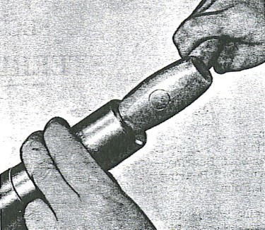
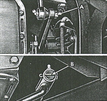
- Remove nut (A) at rear end of drag link, Figure 4, and press ball stud out of pitman arm using puller J-2781.
- Remove pitman arm nut and take off pitman arm using puller J-1374, Figure 5.
- Slide steering gear forward on frame and remove steering gear by pulling chuck upward through engine compartment.
|
FIGURE 4
 |
- Drain lubricant and mount assembly in a vise.
- Remove gear shaft cover (3), Figure 1.
- Cover serration on gear shaft with waxed paper to prevent damage to oil seal and remove gear shaft and roller assembly.
- Remove oil seal (6).
- Remove worm gear cover (13) and grease retainer tube assembly; use care to prevent damage to shims (10).
- Remove lower bearing (15), bearing cup (16), worm and column tube assembly, upper bearing (18) and cup (17). Thoroughly clean inside of steering gear housing and all other parts after disassembly. Carefully inspect all parts for wear and damage and replace where necessary.
|
FIGURE 5
 |
- Assemble upper bearing cup and bearing in housing and install worm and tube assembly.
- Install lower bearing and cup.
- Install worm shaft cover shims and cover and grease retainer tube assembly.
- Install a new gear shaft oil seal (6) in housing.
- Turn high point notch on steering column tube straight down and isntall gear shaft and roller assembly.
- Assemble thrust plate (4) on adjusting screws (5) into slot in gear shaft and install gear shaft cover using new gasket.
- Install lock plate (8) and lock nut (9) on adjusting screw.
- Place pitman arm on gear shaft and tighten to 125 to 140 foot pounds.
- check worm for end play. If end play exists, adjust by removing one worm cover shim 910) at a time until end play is eliminated. Rotate column tube after ech removal to determine if stiffness exists. Stiffness indicates removal of too many shims.
- Check gear shaft for excessive play. If pitman arm can be moved more than 1/32" without turning the steering column tube, remove gear shaft adjustment screw lock nut and lift lock plate clear of the cover boss. (Check notch on steering column tube to be sure it points straight down.)
Tighten adjusting screw just enough to remove play between gear and worm. DO NOT TIGHTEN BEYOND THE POINT OF TAKING UP LASH. Replace lock plate and lock nut and tighten nut.
- Replace felt washer on column tube at steering gear housing.
- Install steering gear assembly on frame and install bolts but DO NOT tighten.
- Install steering gear jacket tube and transmission control parts. Tighten tube in bracket at instrument panel.
- Tighten the three bolts attaching steering gear to frame 50 to 60 foot pounds.
- Loosen bolts attaching steering column bracket cup at instrument panel to allow column to shift to match position of steering gear and retighten bolts.
- Install horn wire and steering wheel with notch in column tube straight down and wheel spokes horizontal. Replace horn button.
- Check front suspension for stiffness by placing front wheels on roller plates an dattaching spring scale to tire tread. Maximum pull required to turn wheels with drag link disconnected is approximately 25 pounds.
- Set front wheels in straight ahead position and connect drag link.
- Fill steering gear housing with S.A.E. 90 E.P. Lubricant.
The drag link has a spherical bearing at the rear end which is spring loaded to take up looseness and wear and incorporates a tapered pivot which enters the hole in the lower end of the pitman arm. The rear end of the tie rod is spun over to secure the bearing parts in place which requires replacement of the drag link and rear bearing as a unit.
The front end carries a threaded plug and spring loaded ball seats contacting the ball on the center steering arm. No shims are provided and the drag link is not adjustable for wear.
REMOVAL
- Remove cotter and nut(A) from drag link stud at piman arm, Figure 4, and disconnect drag link using puller J-2781.
- Remove cotter and plug (B) from drag link at center steering arm and remove drag link.
INSTALLATION
- Set front wheels and steering gear in straight ahead position. Adjust tie rods if necessary to obtrain 0" - 1/16" toe-in.
- Attach front end of drag link to center steering arm and rear end to the pitman arm.
If end play exists in the worm bearings, the following adjustment is necessary.
- Disconnect drag link at pitman arm using tool J-2781.
- Loosen the four worm cover bolts about 1/8".
- Use a knife to separate the top shim.
- Remove one shim at a time and retighten cover.
- After each shim is removed, turn steering wheel through entire radius to determine if any stiffness exists.
- If stiffness if felt, replace shims until steering wheel turns freely.
- Attach drag link to pitman arm.
ROLLER MESH INSPECTION
Improper mesh of roller with worm gear is indicated by excess play or stiffness in the stering wheel. Inspection for proper mesh should not be made until worm bearing end play and gear alignment have been checked and corrected if necessary as follows:
- Disconnect drag link at pitman arm.
- Turn steering wheel to straight ahead positon.
- Shake pitman arm to determine amount of lost motion. If lost motion exceeds 1/32", adjust roller for proper mesh.
- Connect pitman arm to drag link.
ROLLER MESH ADJUSTMENT
- Disconnect pitman arm from drag link.
- Remove left side dust shield.
- Turn steering wheel to straight ahead position.
- Remove roller shaft adjustment screw lock nut and lift lock plate clear of boss on housing.
- Tighten roller shaft adjustment screw just enough to eliminate lost motino at pitman arm. (It is better to leave a slight amount of play - not in excess of 1/32" - than to tighten too much.)
- Replace lock plate against cover in locked position and replace and tighten lock nut.
- Replace dust shoeld and connect drag link to pitman arm.
IMPORTANT: Before connecting drag link to pitman arm, place the front wheels on roller plates and attach spring scale to tire tread. Maximum pull required to turn wheels at any point in the turning radius is 25 pounds. Any excess pull indicates a binding in the front suspension that should be corrected for proper functioning of steering mechanism.
|
REMOVAL
- Remove drag link at front by backing off plug.
- Remove tie rod ends from steering center arm using tool J-2781.
INSTALLATION
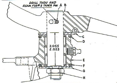
- When installing new bearing in center steering arm bracket, space as shown in Figure 6 and apply pressure on outer race at end carrying manufacturers name and part number.
- If necessary to replace the steering arm pivot, the new pivot should be rpessed in place mantaining the 2.053" to 2.055" dimension as shown before drilling the hole for the No. 5 taper pin (A).
- The rubber seals (F & D), consist of a steel washer bonded to synthetic rubber, therefore a separate retainer is not used.
- When installing the seals the rubber lip faces to the casting as shown in cross section and the spacers (C) and (G) positioned as shown.
- The center steering arm pivot nut (H) should be tightened to 50-60 foot pounds.
Steering center arm installation is the reverse procedure of removal. Tighten the steering center arm bolt with a torsion wrench to 70 foot pounds. |
FIGURE 6
 |
|
HARD STEERING
Insufficient lubrication
Excessive caster
Excessive positive or negative camber
Worn pivot pins or pivots
Bent or broken frame
Sagging or broken springs
Weak rear springs
Low tire pressure
Binding steering assembly
|
LOOSE STEERING
Worn steering linkage
Weak springs in drag link
Worn pivot pins, bushings
Improper stering adjustment
Worn tie rod ends
Worn sector shaft bushing |
WANDER OR WEAVE
Insufficient caster
Incorrect toe-in adjustment
Worn pivot pins, bushings
Worn front wheel bearings
Tight steering assembly
Loose spring shackles
Sagging or broekn springs
Bent or broken frame
Loose rear spring U-bolts
Overloading
Unequal tire pressure or tire wear
|
SHIMMY
Too much caster
Loose pivot pins
Loose drag link arm
Loose steering gear
Low tire pressure
Unequal inflation
Loose wheel bearings
Sagging or broken springs
Worn tie rod ends |
ROAD SHOCK
Unequal or excessive caster
Weak front springs
Bent steering arm (right or left)
Bent drag link
Defective shock absorbers |
SIDE PULL
Unequal caster
Bent steering arm
Bent, broken frame
Tight pivot pins
Weak rear springs
Uneven tire inflation
Oil-soaked brake lining
Sagging front springs |
How do you adjust the steering wheel play on the Jet? Do you have to take the adjusting lock nut off, then remove the plate (4 bolts) to get to the adjustment? Also, what kind of grease or oil is best for the the steering box?
If you haven't already read the Worm Bearing Adjustment section above, please do so, then read on... It is important that you remove the drag link when checking the steering play, as you can then feel the backlash in the drop arm. You need to take the dust cover off, which will allow you to lift the lock washer off. You can then turn the adjustment screw in. Check the play of the drop arm in the straight ahead position. When there is zero backlash, re-install the lock washer and dust cover, and check through the whole movement that there is no binding.
DO NOT use grease to lubricate steering box! The manual specifies EP90 gear oil, but it is permissible to go up a grade to 140.
|