HudsonJet.net |  |
DISCLAIMER: Unless otherwise noted, service information has been provided by an edition of the Mechanical Procedures Manual for Jet models. The data from the Manual includes information covering specifications, adjustments and detailed operation involved in maintenance and repair procedures. After market updates from Hudson Service Merchandisers and other sources have been added as well and are credited in italics. HudsonJet.net provides this reference as a courtesy and is not responsible for any work done using Hudson Motor Car Company's publications or other sources provided on this site. |
|
|
Teeth in Gear
Teeth in Pinion
Standard Transmission
Overdrive Transmission
Hydra-Matic Transmission |
3.31 (3-4/13)
43
13
Optional
----------
Optional |
4.1 (4-1/10)
41
10
Standard
Optional
---------- |
4.27 (4-3/11)
47
11
Optional
Standard
---------- |
3.54 (3-7/13)
46
13
---------
----------
Standard |
|
Axle Shaft End Play
Gear & Pinion Back Lash
Housing Spread for Service
Pinion Bearing Pre-Load Torque
Pinion Front Bearing Shims
Pinion Rear Bearing Shims
Differential Bearing Shims
Wheel Bearing Shims
Lubrication
|
.001" to .006"
.002" to .006"
.020" (max).
10"-20" lbs.
.003, .005", .010", and .030"
.003", .005", and .010"
.003", .005", .010", .030"
.003", .005", .010", .030"
S.A.E. 90 Hypoid or Multi-Purpose Gear Lubricant - 2-1/2 Pints
|
|
The rear axle is the semi-floating type.
The axle has a cast malleable iron housing into which the axle shaft tubes are pressed and welded. An axle housing inspection cover is attached to the rear of the axle housing by ten capscrews.
The differential side gears ride in the case bores and the differential pinions rotate on the pinion shaft, which is locked by a pin through the case and shaft. Treated steel washers are used to take thrust of the differential pinions and side gears.
Thrust of the axle shafts is taken by a spacer block through which the pinion shaft passes. Shims between the differential side bearings and the case control the side mesh of the ring gear and pinion as well as the preload on the differential side bearings.
The drive pinion bearing cups, front and rear, are pressed in the axle housing, and shims behind the rear bearing cup provide proper adjustment for the mesh of the drive pinion with the drive gear.
Another shim pack placed between the front bearing cone and shoulder of the pinino controls adjustment and pre-load of the drive pinion bearings.
Oil forced through passages cast in the housing by the drive gear lubricates the differential assembly and drive pinion.
An oil slinger, and leather seal prevents loss of oil at front of the pinion.
Axleshaft splined ends engage the differential side gears and the outer ends are tapered to retain the axle bearings and wheel hubs.
The bearings are tapered roller bearings having a tapered cone which seat on the tapered shaft. The bearing cups are pressed into the axle housing flange.
Axle shaft end play and wheel bearing adjustment is controlled by shims located between the axle housing flange and the brake backing plate on the right side only.
Inner oil seals are pressed into the axle shaft tubes to prevent axle lubricant from entering the wheel bearings and the wheel bearing cap leather oil seals prevent leakage of wheel bearing lubricant into the brake compartment.
|
FIGURE 1
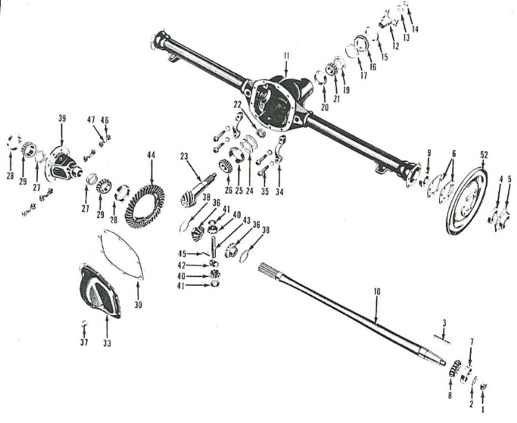 |
FIGURE 2
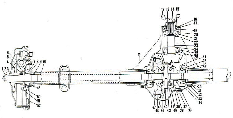 |
| LEGEND |
- Axle shaft nut
- Axle shaft washer
- Axle shaft key
- Wheel bearing adjusting cap oil seal
- Wheel bearing oil seal cap
- Wheel bearing adjusting shims
- Wheel bearing cup
- Wheel bearing cone
- Wheel bearing inner oil seal
- Axle shaft
- Carrier and tube assembly
- Companion flange
- Drive pinion washer
- Drive pinion nut
- Drive pinion dirt shield
- Drive pinion oil seal
- Drive pinion oil seal gasket
- Not Applicable
- Drive pinion oil slinger
- Drive pinion front bearing cup
- Drive pinion front bearing cone
- Drive pinion front bearing shims
- Drive pinion
- Drive pinion rear bearing shims
- Drive pinion rear bearing cup
- Drive pinion rear bearing cone
|
- Differential side bearing shim
- Differential side bearing cup
- Diferential sie bearing cone
- Housing cover gasket
- Housing cover bolt lockwasher
- Housing cover bolt
- Differential housing cover
- Differential side bearing cap
- Differential bearing cap bolt
- Differential gear
- Housing cover filler plug
- Differential gear thrust washer
- Differential case
- Differential pinion
- Differential pinion thrust washer
- Axle shaft spacer
- Differential pinion shaft
- Drive gear
- Differential pinon shaft locating pin
- Drive gear bolts
- Drive gear bolt lock
- Wheel bearing grease hole plug
- Not Applicable
- Wheel bearing adjusting cap bolt
- Wheel bearing adjusting cap nut
- Brake backing plate
|
|
- Raise car on a hoist or use stand jacks. Remove drain plug and drain axle lubricant.
- Remove rear wheel covers and take off rear wheels.
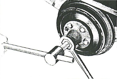
- Remove wheel hubs using puller J-736A (Figure 3).
- Disconnect brake cables at toggle and unhook the brake cables from the parking brake levers.
- Disconnect brake hose at the frame connection and brake lines at wheel cylinders.
- Remove the four backing plate bolts (each side) and remove the backing plates, wheel bearing oil seal caps and the shims (on the right side only). The shims should be tied together until reinstallation.
- Remove axle shafts, using puller J-352B.
- Pull axle shaft oil seals, using puller J-943.
- Disconnect propeller shaft at rear axle companion flange and use masking tape to keep cups from falling off roller bearings.
- Remove nuts from spring clip "U" bolts and lower studs of shock absorbers.
- Use a jack uner the axle housing and raise assembly slightly.
- Lower axle assembly to floor and remove mounting plates, cushions and 'U" bolts; then place axle on bench or axle stand for further disassembly.
|
Figure 3
|
- Thoroughly clean outside of axle housing with a good solvent to preclude the possibility of dirt entering axle housing.
- Remove bolts from inspection cover and remove cover and gasket.
NOTE: Metal tag under one bolt head denotes axle ratio and must be replaced when axle is reassembled. |
- Use a solvent to thoroughly clean inside of housing and all gears and bearings.
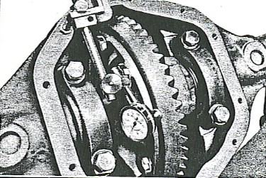
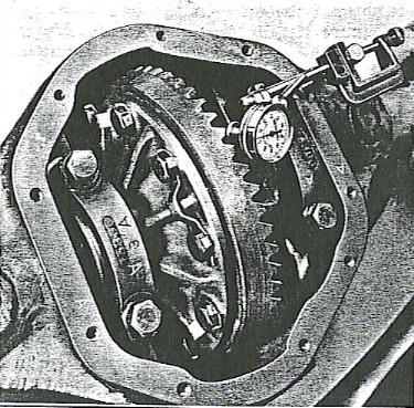
- When axle is clean and before further disassembly, check the drive gear for run-out. Mount a dial indicator as shown, Figure 4, and slowly turn the rear axle rive pinion. If the drive gear run-out is more than .003" check for the possibility of a sprung case, loose drive gear to case bolt or nicks and burrs between drive gear and flange. Remove dial indicator.
- Remove the four bolts and differential bearing caps.
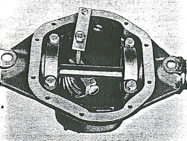
NOTE: Both caps and each side of housing are stamped with a identifying number or letter. On one side the markings will be parallel with each other; on the opposite side, they will bee vertical to each other, Figure 18. |
Figure 4
|
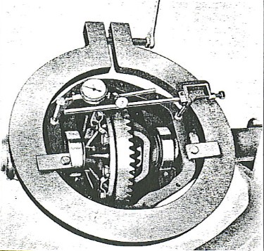
- Install axle housing spread J-5372 in place on housing and mount the dial indicator on housing and mount the dial indicator as shown, Figure 5. Use an end wrench to turn the hex handle of th spreader tool until the indicator reads .020" spread.
NOTE: Do not spread housing more than .020" as it may cause housing to take a permanent set, necessitating replacment of the axle housing.
It is necessary to spread the housing for removal or installation of the differential due to he pre-load of from .005" to .009" between the differential side bearing cups and housing.
|
Figure 5
|
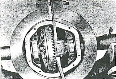
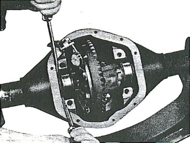
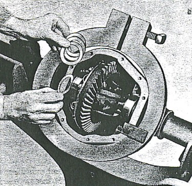
- Remove the differential assembly by prying upward and outward with two large screwdrivers as shown, Figure 6.
- Remove bearing cups from side bearing, if the bearing cups or cones are not damaged or excessivly worn, be sure mating parts are kept together for proper reassembly.
- Remove differential bearing cones from case, using puller J-2241-A with J-2231-10 adapter; remove shims.
NOTE: Keep shim packs together to be reinstalled in same manner.
|
Figure 6
|
- Use a screwdriver and pry up tabs of the drive gear capscrew lock plates, remove capscrews and locks and remove drive gear.
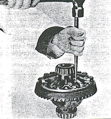
- With a suitable punch drive out lock pin which secures pinion shaft in different case, Figure 7.
- Drive the differential pinion shaft from differential housing and remmove shaft spacer through one of the differential side gears.
- Remove the differential pinions and thrust washers, differential gears and thrust washers.
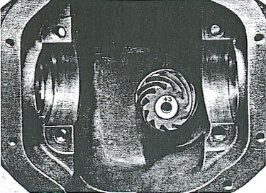
- Turn axle housing so the drive pinion companion flange is in a vertical position.
|
Figure 7
|
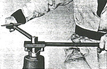
- Remove nut from drive pinion using the J-2637 companion flange holding tool, Figure 8.
|
Figure 8
|
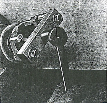
- Remove companion flange, using puller J-820, Figure 9.
- Attach driver J-1373A to threads on pinoin shaft and drive pinion out of front bearing with a brass hammer and a brass drift. Remove the driver from shaft before it contacts the bearing cone and continue tapping drift until pinion can be removed, using care to prevent pinion falling to floor.
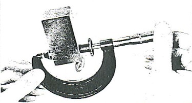
- Remove shim pack from pinion. With a micrometer, check each shim and record total thickness for reinstallation.
NOTE: If necessary, replace pinion shaft cone and rollers using bearing puller J-5365. |
Figure 9
|
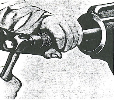
- Remove pinion rear bushing cup from housing using remover tool J-2644 and handle J-872-5 (figure 10). Remove shims from behind bearing cup, check thickness of each shim, record total thickness and tie shims together for reinstallation.
- Use a brass drift to drie out the front pinion bearing cup.
|
Figure 10
|
Thoroughly clean the inside of axle housing. Do not steam clean.
Carefully inspect each part for wear or toher signs of damage such asnicks, burrs, etc.
Examine all bearings carefully. If cone rollers or cups are grovved, pitted or worn, they must be replaced with a new bearing assemblies.
Insect all differential pinions, gears, thrust washers and shaft spacer and case. If pinions or gears appear worn or loose on pinion shaft and in the case, they should be replaced.
Differential cases in which the thrust surfaces are scored, pitted or worn must be replaced.
When necessary to replace drive gear or drive pinion they must both be replaced since they are available only in matched sets and both the gear and pinion carry an identifying number.
Oil and grease seals must be replaced with new parts.
|
ASSEMBLY AND INSTALLATION
- Install differential gears, and pinions, thrust washers in case and cover all contact areas and axle shaft spacer with rear axle lubricant.
- Install the differential pinion shaft and drive in the lock pin, peen case metal over top of pin to lock pin in place.
- Install drive gear on the differential case and insert bolts and lock plates. Use a torque wrench and tighten botls to 50-6- lbs. Bend over lock plate ears.
- Install the differential bearing cones on the differential case hubs without shims using driver J-5364, Figure 11.
|
Figure 11
|
- Clean the bearing cups and place on cones. Be sure cups are not scored, nicked, etc.
- With axle housing in a vertical position, clean bearing bores in housing and install the differential assembly.
- Install the bearing caps in their correct position. Be sure letters or numbers on cap, Figure 18, are in same position as letter or number on housing and tighten bolts finger tight.
- Mount a dial indicator with the control button against back face of the drive gear, Figure 12, insert two screwdrivers between bearing cup and housing and force differential assembly to one side far as possible.
Set dial indicator to zero and shift differential as far as possible to opposite side, note and record reading on indicator.
This reading denotes the shim requirements between the differential assembly an the bearing cones to be installed later. |
Figure 12
|
- Remove the side bearing caps and remove the differential assembly.
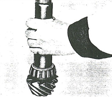
- Observe the figures etched on the rear end of the drive pinion. One set of numbers will be found identical on both the drive gear and pinion, which denotes a matched set. Another figure will be found on the end of drive pinion which shows a plus or minus sign, Figure 13. This indicates the position of the pinion in relation to the center of the axle. If there are no figures showing a plus or minus sign, it denotes a zero pinion setting and a zero "0" will be shown.
|
Figure 13
|
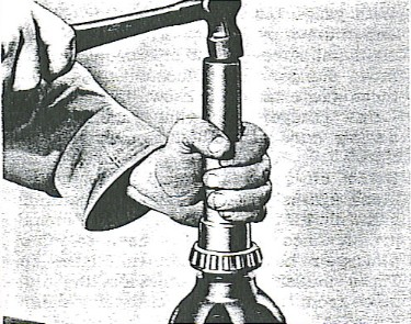
- Install drive pinion rear bearing cone and rollers using J-2643 cone replacer, Figure 14.
- Install pinion rear bearing cup, using tool J-2645 and handle J-872-5, placing shims between cup and housing.
The amount of shims used is determined by the amount of shims removed at disassembly and by the plus or minus figure etched on pinion. For example, if the original pinion was marked +2 and had a shim pack of .035" behind the rear bearing cup, and the new pinion to be installed is marked -1, the shim pack must be increased by .003" to bring the new pinion to its correct position. The new shim pack will, therefore, be .038" thick. Shims for the rear pinion bearing are available in .003", .005", and .010" thickness.
- Install the drive pinion front bearing cup, using replacer J-5367. Insert the drive pinion in position and install the front bearing cone and rollers. Coat bearing with axle lubricant.
|
Figure 14
|
- Make sure the differential bearing bores in housing are clean. Mount discs of pinion setting gauge J-5223 on gauge arbor and install gauge in housing bores, Figure 15. Place differential bearing caps i position and tighten bolts finger tight.
- With gauge block held in position against end of drive pinion by clamp screw, loosen thumb screw in end of gauge block and move plunger out of block until head contacts gauge arbor as shown in Figure 15. Lock plunger by turning thumb screw, using care not to disturb plunger position.
|
Figure 15
|
- Back off screw in clamp holding gauge block against pinion, remove gauge block and with a 2 to 3 inch micrometer, measure idtance from end of anvil to top of plunger head as shown in Figure 16. This measurement represents the distance from the rear face of the drive pinion to the center line of the rear axle and should be 2.343" for the 11 tooth, 4.27:1 ratio and 13 tooth 3.54:1 and 3.31:1 ratio pinions. For the 10 tooth, 4.1:1 ratio pinion this measurement should be 2.250". These measurements apply to crrectly adjusted pinions carrying zero "0" markings. With a pinion marked +2 the reading should be .002" less than these figures and for a pinion marked -3, the reading should be .003" greater.
|
Figure 16
|
- If the micrometer reading shows the pinion setting is incorrect by more than .002" plus or minus from the given figures, shims equal to that difference must either be added to or removed from the shim pack between the rear bearing cup and housing.
When changing shim packs, it is advisable to check each shim separately to avoid unnecessary removing and installing of pinion and depth gauge.
- When the correct pinion setting is accomplished, install the pinion front bearing shims on shaft and install the front pinion bearing cone and rollers.
- Install companion flange washer and nut, holding flange with J-2637 holding tool. Tighten pinion nut to 180-200 ft. lbs.
- Use a spring scale on the J-2637 holding tool and check torque required to turn pinon. The turning torque should be from 10 to 20 inch pounds. If the reading varies more or less, it will be necessary to add or remove shims from the front bearing shim pack. The shims are available in .003", .005", .020" and .030".
- When the proper pre-load is et, remove the pinion nut, washer and companion flange.
- Install the oil slinger, and install a new gasket incounterbore at front of housing.
Install new oil seal with rear face against gasket using Oil Seal Installer J-5366.
- Reinstall companion flange, washer and nut, torque to 180-200 ft. lbs.
- Inspect differential side bearing cones and cups as well as bearing bores in housing to be sure all are free of dirt and grit. Place cups on cone and rollers and lubricate thoroughly. Install differential assembly in housing.
- Replace bearing caps in their proper position according to markings and tighten bolts finger tight.
- Insert two screwdrivers between bearing cup and housing on the sie opposite the drive gear and move the differential assembly and drive gear away from the pinion until the opposite bearing cup is firmly seated aginst housing. Move the screwdrivers to the drive gear side and force the differential assembly and drive gear over until drive gear teeth contact the pinion teeth.
|
- From shim requirements shown by indicator reading (Paragraph 8, above) place shims between bearing cups and housing, Figure 17, dividing total amount of shims between sides to eliminate all backlash.
- Remove bearing caps and take out differential assembly and drive gear, keeping each shim pack separate. use bearing puller J-2241-A, with J-2241-10 adapter, remove the bearing cones from differential case and install the shim packs on their respective hubs. Install an additional .015" thickness of shims behind the differential bearing on the tooth side of the drive gear to provide the proper backlash between the gear and pinion and also provide the proper bearing pre-load. Install bearings using Installer J-5364. Lubricate thoroughly.
- Place axle housing spread J-5372 in position, mount the dial indicator and spread housing .020" as shown in Figure 5 to permit installation of the differential assembly.
- Install differential and bearings in housing to insure proper seating in bearings, tap drive gear lightly with a rawhide hammer.
|
Figure 17
|
- Install the bearing caps and use sealing compound on the bolt threads. Be sure identifying marks on caps and housing are aligned, Figure 18.
- Remove housing spreader tool and torque bearing cap bolts to 70-90 ft. lbs.
- Install the dial indicator on housing withcontact button resting against edge of gear tooth and check the backlash between drive gear and pinion. Backlash is .002"-.006" and should not vary more than .002" between positions checked.
- Install the inspection cover, using a new gasket and replacing the ratio tag under one of the capscrews.
|
Figure 18
|
[All 1953 HUDSON MODELS]
as suggested in Hudson Service Merchandiser Vol. 5, No. 6, June, 1953
In the replacement of a rear axle drive gear and pinion set, three things are vitally important for quiet operation and satisfactory wear. They are preload of the pinon and differential case bearing, back lash between gear and pinion and depth of pinion mesh.
The method of obtaining these adjustments is fully explained and illustrated [here] in the Rear Axle Section [as seen above]. Listed below are the measurements between the rear face of pinion and center line of rear axle for the various rear axle ratios. It is suggested this data be posted in the Rear Axle Section of your manual.
DRIVE GEAR
& PINION PART NO.
308525
308530
308580
309263
309435
306981
307564
307567
309438
309432
309429 |
CAR
MODEL
1C-2C
1C-2C
1C-2C
1C-2C
4-5-7-C
4-5-7-C
4-5-7-C
4-5-7-C
4-5-7-C
4-5-7-C
4-5-7-C |
AXLE RATIO
4.10 (4 1/10)
4.27 (4 3/11)
3.31 (3 4/13)
3.54 (3 7/13)
3.92 (3 11/12)
3.07 (3 1/14)
4.09 (4 1/11)
4.55 (4 6/11)
4.27 (4 3/11)
3.53 (3 7/13)
3.31 (3 4/13) |
PINION
TEETH
10
11
13
13
12
14
11
11
11
13
13 |
GEAR
TEETH
41
47
43
46
47
43
45
50
47
46
43 |
PINION
DEPTH
2.250
2.343
2.343
2.343
2.625
2.625
2.625
2.625
2.625
2.625
2.625 |
When making installation of a new gear and pinion set, be sure to observe the number preceded by a plus or minus sign etched on the rear face of pinion. This indicates the position of the pinion in relation to the center of the acle. If there are no figures showing, a plus or minus sign, it denotes a zero pinion setting and a Zero "0" will be shown.
DIFFERENTIAL CASE
The various number of teeth in the drive gear and pinion affects a wide variatino in the thickness of these parts and in order to provide for space, two separate differential cases are supplied for the various gear ratios of the 1C and 2C. Also two for the 4-5 and 7C.
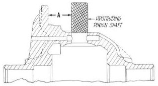
Unfortunately, there are no identification marks on any of these case assemblies other than a part number tag. In order that they may be distinguised, in event the number tags are lost or when shipping differential cases when the gear ratio is known (which is very important), the measurements as shown in the following illustration wills erve to properly identify these.
Measurement "A" is made from the flange of the differential case to which the drive gear is bolted to the protruding pinion shaft. Although there are two identical measurements, one on the 1 and 2C and one on the 4-5 and 7C, the 1C and 2C have the smaller differential case.
|
|
MODEL
1c & 2c
1c & 2c
4c-5c-7c
4c-5c-7c
|
GEAR
RATIOS
4.10-4.27
3.31-3.54
3.92-4.09
4.27-4.55
3.07-3.31
3.53 |
DIFFERENTIAL
CASE ASSEMBLY
308524
308523
307571
307000 |
MEASUREMENT
AT POINT "A"
13/16"
1"
13/16"
1 1/8" |
|
AXLE SHAFT
INSTALLATION
NOTE: If axle shaft bearing requires replacement use J-5368 Remover and J-5369 Installer.
- Install axle shaft inner oil seal using installer J-5370.
- Install the axle shafts. use care when inserting axles in housing not to damage the new inner oil seals. Lubricate the wheel bearings and start outer cups into housing by tapping witha rawhide hammer. Use flange bolts and brake backing plates to draw cups into place.
- Insert the four attaching bolts and install shim pack (right side only) between the brake backing plate and flanges.
- Install wheel bearing oil seal caps, bolts, lockwashers and nuts. Install new oil seals in caps and tighten bolt nuts to 12-17 ft. lbs. torque.
- Check the axle shaft end-play, which should be .001" - .004". If necessary to adjsut end-play, change shims on right side as necessary to obtain correct end-play. Axle adjusting shims are available in .003", .005", .010" and .030".
INSTALLATION
- Place axle assembly in position on rear springs an dinsert retainers and rubber cushions under spring seats. If the rubber cushions are deteriorated, install new onew. Be sure heads of spring center bolts engage holes in spring seats.
- Install rear axle "U" bolts and lower spring plates, nuts and lock nuts. Torque nuts to 70-80 ft. lbs.
- Place a roller jack under the axle housing and raise housing sufficiently to connect both shock absorbers.
- Remove masking tape from universal joint needle bearing cups and install "U" bolts, washer and nuts. Tighten nuts to 14-17 ft. lbs. torque.
- Connect brake lines at wheel cylinders, hose at frame connections and bleed the brakes.
- Connect the parking brake cables to levers.
- install brake drum and hub assemblies on axle shafts. Install washers and axle shaft nuts, tightening to 125-175 ft. lbs. torque. Install cotter pins.
- Install wheels and tighten hub bolts to 60-65 ft. lbs. torque. Install hub caps.
- Remove axle housing inspection cover filler plug and fill housing to level of plug opening (2-1/2 lbs.) of S.A.E. hypoid or multi-purpose gear lubricant. Replace plug and tighten both filler plug and drain plug.
- Install rear wheel covers and lower car to floor.
REAR AXLE HOUSING
Part No.
| Name
| Per Car
|
Replace with...
|
| C 308533 |
Housing Assembly - Less Backing Plates
Bolts for rear wheel bearing adjusting cap secure
brake back plate. See Rear Sheel Bearings.
|
1 |
|
BX 170975
BX 170976 |
Bolt - Diferential Bearing Cap
Lockwasher Differential Bearing Cap |
4
4
|
|
BX 308560
BX 308561
BT 395
BT 70414 |
Cover - Rear Axle Differenial
Gasket - Rear Axle Differential Cover
Bolt - Cover to Axle Housing
Lockwasher - Cover to Axle Housing Bolt |
1
1
10
10
|
See Figure 1, Number 33.
See Figure 1, Number 30. |
BX 1491
BX 322
BZ 9773 |
Plug - Rear Axle Drain
Plug - Rear Axle Cover Filler
Plug - Rear Wheel Bearing Grease Filler |
1
1
2 |
Figure 1, Number 37. |
BZ 308359
BZ 71295 |
Bumper - Rear Axle (On Frame)
Bolt - Axle Bumper Tapping |
2
4 |
 |
Axle Rear Seal: CR(Chicago Rawhide) 11366 or National 18402
Pinion Seal: CR 15788 (Chicago Rawhide), National #5778
|
|
|
|
Courtesy HET JetSet - All Rights Reserved.
|
|