Hudson Jet | 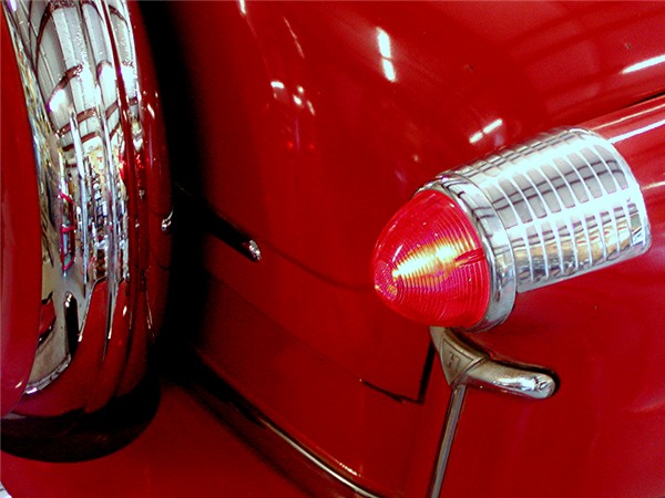 |
DISCLAIMER: Unless otherwise noted, service information has been provided by an edition of the Mechanical Procedures Manual for Jet models. The data from the Manual includes information covering specifications, adjustments and detailed operation involved in maintenance and repair procedures. After market updates from Hudson Service Merchandisers and other sources have been added as well and are credited in italics. HudsonJet.net provides this reference as a courtesy and is not responsible for any work done using Hudson Motor Car Company's publications or other sources provided on this site. |
|
Overdrive provides a driving ratio of engine speed to rear wheel speed that is numerically lower than direct drive. In overdrive, the engine revolves 30% slower than in direct gear at the same car speed, resulting in less wear on engine parts as well as greater fuel and oil economy and smoother operation at high speeds.
SERVICING UNITS REQUIRING REMOVAL OF OVERDRIVE HOUSING ONLY
Repairs to the overdrive case, overdrive mainshaft, mainshaft ring gear, free wheeling cam, pinion cage assembly, stationary gear, shift rail and fork assembly, overdrive mainshaft rear bearing, overdrive mainshaft oil seal, speedometer drive gear, solenoid pawl and interlock plunger may be performed underneath the car by removing the overdrive housing without disturbing the transmission. See "Overdrive Housing Removal", below. However, if the transmission mainshaft, overdrive adpater, or transmission mainshaft bearing are to be replaced, it will be necessary to proceed as outlined uner "Transmission and Overdrive Removal".
OVERDRIVE HOUSING REMOVAL
- Place car on stand jacks.
- Remove drain plugs and drain transmission and overdrive cases.
- Disconnect governor switch wire at control switch, also two wires at solenoid.
- Remove nuts and washers from "U" clamps attaching propeller shaft universal cross to rear axle pinion companion flange.
- Lower rear end of propeller shaft and pull complete assembly backward out of transmission.
NOTE: Use masking tape to hold bearings to universal joint.
|
- Remove speedometer cable and speedometer driven gear.
- Disconnect overdrive control cable at control shaft lever.
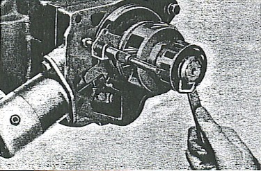
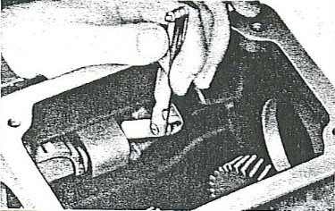
- Drive out the overdrive control shaft tapered pin, Figure 1, and pull control shaft out as far as possible to disengage the operating cam of the shift shaft from the slot in shift rail.
NOTE: Small end of taper pin is down.
- Remove the three bolts and lock washers and remove the mainshaft rear bearing retainer.
- Remove the four bolts attaching the overdrive housing to transmission and overdrive adapter.
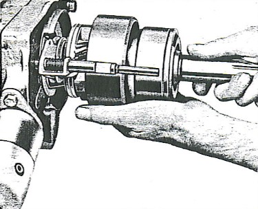
- Remove the overdrive mainshaft rear bearing snap ring (105) and spacer washers (104), Figure 2.
- Remove overdrive housing. (Lightly tap the end of the overdrive mainshaft with a rawhide mallet to prevent mainshaft from coming off with the overdrive housing and spilling the free wheeling roller.)
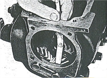
NOTE: Removal of the overdrive housing will expose the governor gear, speedometer gear, overdrive mainshaft and ring gear free wheeling cam, pinion and cage assembly, shift rail and fork, stationary gear, stationary gear cover plate and overdrive mainshaft bearing.
|
FIGURE 1
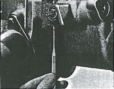 |
FIGURE 2
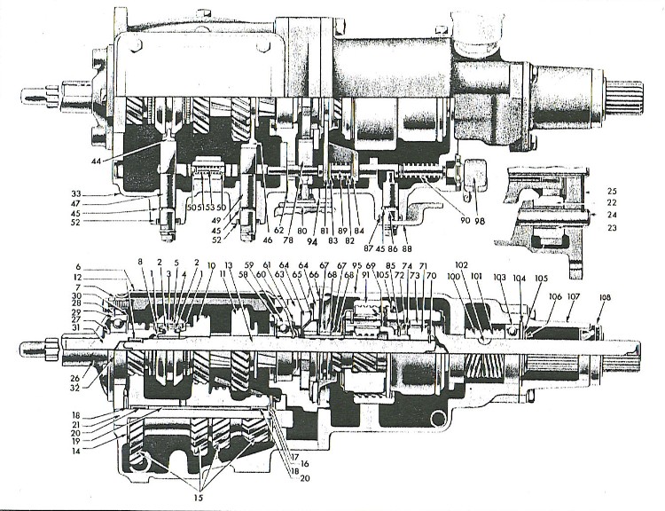 |
FIGURE 3
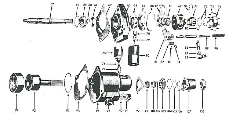 |
| LEGEND |
- Mainshaft
- Trans. mainshaft snap ring
- Tans. mainshaft bearing
- Trans. mainshaft snap ring
- Bearing oil baffle
- O/D to trans. case gasket
- Overdrive housing adapter
- Sun gear plate and balk ring
- Sun gear plate cover
- Cover plate snap ring
- Sun gear snap ring
- Sun gear and shafting collar
- Pinion cage assembly
|
- Pinion cage retainer
- Cam assembly
- Cam roller retainer springs
- Cam roller
- Cam roller retainer
- Governor switch
- Lock ring
- Governor pinion
- Sun gear pawl
- Sun gear pawl oil seal
- Solenoid assembly
- Shift fork
- Shift rail sleeve spring
|
- Lockup rail "C" washer
- Lockup rail washer cup
- Cam retainer clip
- Control shaft
- Control shaft oil seal
- Control lever
- Shift rail
- Shift rail retractor spring
- O/D mainshaft ring gear
- O/D mainshaft output shaft
- Snap ring
- Overdrive housing gasket
- Overdrive housing
|
- Control shaft locating pin
- Control switch gasket
- Control switch
- Retainer gasket
- Governor drive gear
- Speedometer drive gear
- Woodruff key
- Rear bearing
- Rear brg. retainer snap ring
- Rear bearing spacer washer
- Output shaft snap ring
- Rear bearing retainer
- Output shaft oil seal
|
|
|
- Intall one bolt removed from housing to hold the adapter plate to the transmission case.
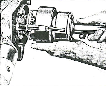
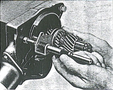
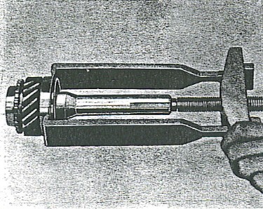
- Remove the overdrive mainshaft and ring gear assembly, Figure 4, (Catch the rollers as they drop out of the free wheeling cam roller retainer).
|
FIGURE 4
 |
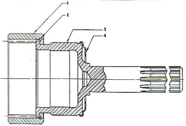
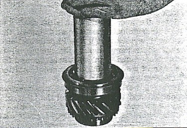
- Removing lock ring (2), Figure 5, will permit the removal of the ring gear (1) from the overdrive mainshaft (3); the oil collector ring (4) is spun securely to the mainshaft to form an oil tight seal.
|
FIGURE 5
 |
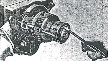
- Remove the retaining clip at the end of the clutch cam, Figure 6, this will allow removal of the camand the pinion cage assembly.
|
FIGURE 6
 |
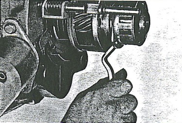
- Remove the "U" clip located between the free wheeling cam and pinion cage and separate these units, Figure 7.
|
FIGURE 7
 |
- Remove the sun gear and shift rail assembly, Figure 8.
|
FIGURE 8
 |
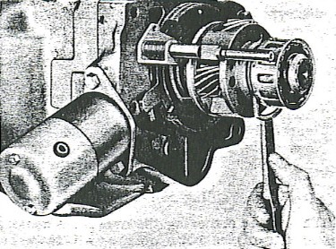
- Remove the solenoid attaching screws, turn the solenoid one-quarter turn clockwise and remove, Figure 9.
|
FIGURE 9
 |
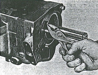
- Remove the large snap ring at the adapter plate, Figure 10.
|
FIGURE 10
 |
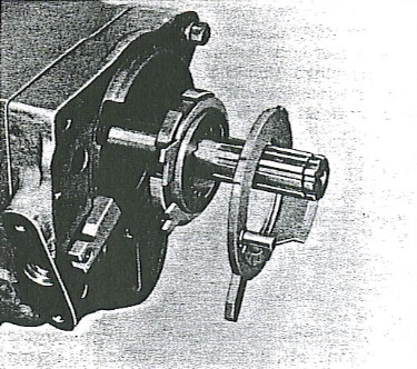
- The retainer plate, the sun gear, control plate and blocker assembly, and the pawl can then be removed, Figure 11.
|
FIGURE 11
 |
As each part is removed from the assembly, wash it with clean solvent and wipe dry. Protect aprts from subsequent dirt accumulation.
After cleaning, give parts visual inspectino for wear or damage. Replace any broken or excessively worn parts.
Roller clutch parts should be carefully inspected. If rollers show surface markings of any kind they should be replaced. If inner surface of the outer roll shows slight lengthwise indentations, they are normal and do not impair the action of the clutch. however, if the 12 flat surfaces of the cam show such markings, it should be replaced.
Inspect fit and tension of the balk ring on hub as follows:
- When pushing one end of balk ring away from opposite end, ring should slide around the hub.
- Push one end toward the other, the balk ring should grab and hold to the hub. If the ring does not hold, it should be replaced.
Test the tension of the cam retaining springs after the cam assembly has been thoroughly washed. The springs are designed to twist the cam in a clockwise direction to hold the rollers up on the cam.
NOTE: If the spring tension is weak ro retarded, the unit will free-wheel at all times.
To check spring tension, hold hub of cam and turn roller retainer counter-clockwise; suddenly releasing the retainer should cause the retainer to spring back quickly. If the action is slow or retarded, replace springs or complete assembly.
BEARINGS
DO NOT place bearings where dirt is liable to mix with the lubricant in the bearings.
Bearings should be washed in clean gasoline or kerosene. DO NOT SPIN the bearings and particulary do not spin bearings with an air hose. Spinning a bearing at high speeds will almost certainly do considerable damage. After washing the bearings, blow then out with clean dry air. Direct the flow of air into the open face of the bearing while holding the inner race and slowly rotate the outer race by hand. DO NOT ALLOW the air to spin the bearing.
- Inspect the bearing for cracks and defects.
- Lubricate the bearing with clean, new engine oil, rotating the bearings by hand in order to spread the lubricant over all surfaces.
Transmission mainshaft bearings are built originally with end play and although they may feel quite loose, it does not necessarily indicate that they are worn and unfit for use.
GEARS
Inspect all gears for damaged teeth. Remove any and all raised edges from tooth surfaces by hand stoning. Pitted and worn gears should be replaced.
CONTROL SHAFT AND SEAL
Recommended clearance between control shaft and overdrive housing bore is .001" to .003" but clearance of twice this amount if not accompanied by oil leakage is permissible.
If a new control shaft seal is installed make sure that it does not interfere with rotaion of control shaft.
If the seal is hard, cracked, or glazed, or if signs of oil leakage are apparent at disassembly, install a new seal.
- Compress the lockup rail spring, pressing it away from the "C" washer (83), Figure 2, and remoe the "C" washer.
- Pull the shift rail shaft out of the shift fork and remove the spring and plain washer.
NOTE: The retractor spring should have a free length of 2-3/4" and 1-21/32" under load of 12 lbs. The lockup rail spring has a free length of 1-3/8" and 15/16" under load of 8 lbs.
- Install the overdrive mainshaft rear bearing and rear bearing lock ring.
- Install a new oil seal in the overdrive rear bearing retainer using Hudra-Matic Rear Bearing Retainer Oil Seal Installer J-1354.
- Before installing the shift shaft in the overdrive housing, coat the shift shaft oil seal counterbore with white lead and tap in a new oil seal. Dip the threaded end of the shift shaft in liquid soap, and using care, push the shaft through the new seal, turn the shaft so that the shifter lug will be in an upright position.
- Install one of the overdrive housing attaching screws to hold the adapter in position. Install the solenoid pawl, sun gear control plate and blocker assembly, Figure 11.
- Install the adapter lock ring (large), Figure 10.
- Install the solenoid by turning the solenoid counter-clockwise one quarter turn, Figure 9, and before installing the cap screws pull straight out on solenoid. If the solenoid can be pulled out, the ball at the end of the solenoid rod was improperly installed (not locked in the pawl).
- Install the locking rail spring, "C" washer and plain washer on the shift rail and fork assembly.
- Install the fork in the sun gear shift collar, and while holding the shift fork, shift rail and sun gear together, slide the sun gear onto the main shaft and the shifter rod in to the hole in the overdrive adapter.
|
INSTALLATION OF CLUTCH CAM, PINION CAGE AND OVERDRIVE MAINSHAFT
- Install the clutch cam and pinion cage, attach the clutch cam to the pinion cage assembly with the large retaining clip, Figure 12.
| Figure 12
 |
- Install the pinion cage and the clutch cam assembly on the main shaft and secure the assembly in place with the retaining clip, Figure 13.
NOTE: Replace any "U" clips that are worn or damaged.
- Install the ring gear (1), Figure 5, on the overdrive mainshaft (3) and lock it in place with the large snap ring (2).
| Figure 13
|
NOTE: To facilitate installation of the mainshaft (output shaft) on the free wheeling cam rollers, insert the free wheeling rollers in teh cam roller retainer cage, using heavy grease to hold them in position. Then, with the low gear of the transmission engage, turn the cage and rollers counter-clockwise until the rollers are in their low positions, and snap a tight fitting rubber band around them. Install the output shaft and ring gear on the pinion cage and free wheeling clutch cam and roller unit assembly, turning the shaft to the left as it assembles over the clutch rollers, Figure 14.
|
Figure 14
|
INSTALLATION
- Remove bolt holding adapter to transmission case.
- Install overdrive to adapter gasket.
- Install overdrive case.
- With the control switch removed, insert a long thin drift through the housing at the control switch opening to line up the retractor spring and the overdrive shift rail.
- While case is being installed, push the control shaft inward and engage the slot in the shift rail with the shifter shaft lug. (Lug must be up and outside control lever down.)
- Install the four overdrive housing to transmission case bolts and tighten all bolts evenly. Tighten all 4 bolts to 20-30 ft. lbs. torque.
- Install the control shaft locating pin, large end up.
- Install control switch, governor pinion, and governor switch.
- Add lubricant to get proper level in both transmission and O.D. units.
REMOVAL
- Remove drain plugs and drain lubricant.
- Remove the nuts, washers and clamps from the rear axle companion flange and drop the propeller shaft and withdraw propeller shaft with sleeve yoke assemlby from transmission.
NOTE: use a rubber band or tape to hold bearing cups and needle roller in place.
- Disconnect the low and reverse and the high and intermediate shift rods at the transmission shifter levers.
- Disconnect the speedometer cable at transmission and the governor wire at the overdrive control switch.
- Disconnect the overdrive control cable from the overdrive shift shaft lever.
- Remove the two screws attaching the clutch cross shaft support assembly to the bottom of the transmission case and remove the support.
- Remove the governor and governor driven gear and the speedometer driven gear.
- Using a universal socket on a 10" extension, remove the top bolts attaching the transmission case to clutch housing. Install two J-2969 Guide Studs to support transmission when removing the two lower bolts.
- Remove the transmission and overdrive assembly, using care not to damage the main drive gear splines and pilot during removal.
- Install transmission i a bench holding fixture and if transmission has not been drained at removal, do so before disassembly.
- Remove the transmission cover and gasket.
- Remove the two screws and washers and remove the overdrive control switch and gaasket.
- Use a pin punch and drive out the overdrive control shaft tapered pin, Figure 1. Pull the control shaft outward approximately 3/8" to disengage the operating cam of the shift shaft from the slot in the rail.
- Remove three screws and washers and remove the output shaft rear bearing retainer and gasket.
- Remove the mainshaft bearing snap ring and spacer.
- Remove the four bolts, 5/8" socket, attaching the overdrive housing to the transmission and overdrive adapter.
- Slide the overdrive housing rearward carefully. Lightly tap the end of the overdrive mainshaft with a soft hammer to prevent the mainshaft from coming off with the overdrive housing and spilling the free wheeling rollers.
NOTE: After removing the overdrive housing install one of the bolts removed from the housing to hold the adapter plate to the transmission case.
- Remove the speedometer gear and governor gear from the output shaft. (Do not lsoe the Woodruff Key).
- Remove the overdrive mainshaft and ring gear assembly, Figure 4, (Catch the rollers as they drop out of the free wheeling cam roller retainer.)
- Removing the retaining clip at the end of the clutch cam, Figure 6, will allow removal of the cam and pinion cage assembly.
- Remove the "U" clip located between the free wheeling cam and pinion cage and separate these units, Figure 7.
- Remove the sun gear and shift rail assembly, Figure 8.
- Remove the solenoid by turning the solenoid one-quarter turn clockwise, Figure 9.
- Remove the large snap ring at the adapter plate, Figure 10, and remove the retainer plate, the sun gear, control plate and blocker assembly and solenoid pawl, Figure 11.
NOTE: With a small pointed brush, paint a fine line across the synchronizer rings, sleeve and the second and high gears to facilitate proper assembly of these parts in reassembly, Figure 4.
- Remove the one bolt previously used to hold the adapter to the case ans using a soft hammer, tap the front side of the adapter plate to release the adapter plate from the transmission case and then pull the complete main shaft and adapter plate rearward to release the mainshaft from the main drive gear pocket bearing.
NOTE: The synchronizer sleeve will slide off the synchronizer hub and the synchronizer shifter plate may drop into the case.
- With a brass drift against the gear face of the main drive gear, drive the main drive gear and bearing assembly towards front of the mainshaft and removal of the synchronzier sleeve.
- Shift the low and reverse shifter fork to the rear (reverse) positin, tilt mainshaft assembly to the right side of case and remove the low and reverse shifter fork.
- Remove the mainshaft and adapter as an assembly.
- Remove the synchronizer sleeve and second and high shifter fork.
- Using a brass drift move the countershaft rearward just enough to free up the lock plate in the shaft groove.
- Use a dummy countershaft 11/16" diameter 5-7/8" long, place end of dummy shaft against the front end of the countershaft and carefully drive the countershaft rearward out of transmission case.
CAUTION: Be sure the dummy shaft remains in constant contact with the countershaft during removal operation, otherwise the thrust washers, needle rollers and spacer will fall out of place.
|
- Remove the main drive gear, bearing and snap ring as an assembly.
NOTE: If replacement of the main drive gear bearing is necessary, use Puller J-1134H with thimble removed as shown in Figure 15.
| Figure 15
 |
Install bearing with Driver J-2995-1, Figure 16.
- With the dummy shaft holding the needle rollers and thrust washers in position, lift the countershaft gear cluster up an out of transmission case.
NOTE: Remove the thrust washers from cluster gear notig position to insure exact replacement.
- Using a long brass drift, drive the reverse idler gear shaft out of rear of transmission case and remove idler gear.
- Drive out tpaer pins (96), Figure 2, securing the transmission shift shafts, (small end of taper pin is down).
- Remove nuts, washers and levers from shift shafts and take shafts out of case. When doing this, also remove interlock sleeve, detent balls, spring and pin.
| Figure 16
 |
- Thoroughly clean both the transmission and overdrive cases.
- Replace shift shaft oil seals by drivinng out the old seals from the inside of the transmission case using a pin punch. Coat outside of new seals and inside of housing bores with red or white lead or gasket sealer and tap new seals in place. Install the low and reverse shift shaft into trnasmission case. Do not damage the oil seal. Align the neutral detent of shift shaft cam with interlock opening in case and install retainer pin.
- Install the interlock sleeve in the case and instal one interlock ball, the interlock spring and interlock pin.
- Enter the second and high shift shaft into the transmission case and install the other interlock ball in the interlock sleeve and while compressing the spring, slide the second and high shift shaft toward the center of the case into its correct position and install retaining pin.
|
- Rotate either shift shaft into any in-gear position and with one end of the interlock sleeve contacting one of the cams on either shift shaft, use a feeler gauge and measure the clearance between the opposite end of the interlock sleeve and the cam of the other shift shaft, Figure 17. This clearance should be from .001" to .007". If the clearance is not within these limits remove the shifter shafts and replace the sleeve with one of the proper length.
NOTE: Interlock sleeves are furnished in five different lengths as follows:
Marking On Sleeve
"A"
"B"
"C"
"D"
No Mark | Length
1.295"
1.291"
1.287"
1.303"
1.299" |
|
Figure 17
 |
- Install the needle roller spacer tube over the special dummy shaft. Apply viscous grease on shaft and insert the shaft and tube in the cluster gear bore.
- Insert needle rollers i position between insdie of gear and dummy shaft (each end of spacer tube) and follow with a retaining washer at each end.
- Coat countershaft thrust washers and ends of gear cluster with viscous grease and place washers into position. Install the front washer with the bronze side facing the gear and the lug on washer pointing up. Install the rear inner (bronze) washer so taht the lugs on the washer will engage the slots in the cluster gear and the outer (steel) thrust washer with the lug pointing up.
- Carefully lower the cluster gear assembly into position in the transmission (lugs on washers pointing up) and enter front end of the countersahft at rear of transmission case, tapping it forward while holding the countershaft in constant contact with the dummy shaft to keep the needle rollers and washers in place.
NOTE: Drive the countershaft forward jsut far enough to enter the front end of countershaft in the case as the countershaft must again be removed after checking countershaft end play.
|
- Check countershaft gear end play by inserting a feeler gauge between the rear thrust washers as shown in Figure 18. End play should range between .006" and .016".
- After checking for proper end play, enter the dummy shaft in front of transmission case and carefully tap out the countershaft through rear of case. After the countershaft has been removed, lower the cluster gear with dummy shaft to bottom of case.
- Install the reverse idler gear in the case (long hub of gear toward front of case) and drive the reverse idler gear shaft in from rear of case.
NOTE: Before fully installing the shaft, make sure the slot in shaft is properly aligned with the slot in countershaft so that the lock plate will seal properly.
|
Figure 18
|
- Check idler gear end play; should be .003" to .010".
- Install the second an dhigh shift fork in the second and high shifter shaft.
- Install the transmission mainshaft bearing and oil slinger (lip to inside) on the mainshaft and in the overdrive adpater and install the large retaining snap ring.
NOTE: These snap rings are furnished in four thicknesses, select the ring of the proper thickness.
- Install the low and reverse sliding gear (shifter collar of gear to rear of transmission).
- Install the mainshaft second speed gear assembly on the mainshaft.
- Assemble the synchronizer clutch hub, shift plate, shift sleeve, springs and synchornizer rings together as a unit and install the assembly on the shaft with long end of the synchronizer clutch hub to front of transmission.
NOTE: Be sure that marks painted on the synchronizer parts during disassembly are properly aligned at re-assembly, also that the hooked ends of the two synchronizer springs engage in the same shift plate.
- Install the snap ring on front of mainshaft and check end play by inserting a feeler gauge between the rear face of the mainshaft second speed gear where it butts up against the mainshaft (at ends of mainshaft spiral splines). This end play should be from .003" to .016". Excesive end play at this point can only be corrected by installing new parts.
- Install new adapter plate to transmission gasket and install the mainshaft assembly with the adapter plate; engage the second and high shifter fork in the shift sleeve, then pull mainshaft towards side of case sufficiently to install the low and reverse shifter fork; offset to rear.
- Install main drive gear bearing on the main drive gear using Driver J-2995-1, Figure 16, and install the snap ring to retain the bearing on the main drive gear. Make sure the proper thickness snap ring is used.
NOTE: The main drive gear snap rings are furnished in the following thickness: .087", .090", .093", .096" and .103".
The main drive gear bearing snap rings are furnished in .073" and .076" thickness.
- Coat inside of mainshaft drive gear and mainshaft front rollers with viscous grease and assemble rollers in positin in the gear.
- Install the mainshaft drive gear and bearing assembly into the front bore of transmission, tapping outer race of bearing with a rawhide hammer until the snap ring in the outer race is flush with front of case.
- While holding pilot end of mainshaft engaged in pocket bearing of the main drive gear, carefully tip the complete transmission so that the transmission will rest on the gasket face of the transmission cover opening. This will allow the countershaft gear to align with the countershaft holes in the case.
- With the countershaft gear cluster in position, swing the overdrive adapter plate to one side and enter the countershaft through rear of case, tapping it forward and pushing the dummy shaft out through front of case.
NOTE: When installing the countershaft, keep the dummy shaft and countershaft in contact with each other and line up slot in rear end of countershaft for proper installation of lock plate.
- Pull mainshaft and adapter plate rearward 5/8", place lock plate in correct position engaging slots at end of counter shaft and reverse idler gear shaft. After installing lock plate, tap both shafts until the lock plate is tightly held.
- Position the adapter plate to the transmission case making sure pilot end of mainshaft is entered properly in bearing in main drive gear pocket and taht shifter forks are properly engaged in the synchronizer shift sleeve and low and reverse sliding gear. Enter one attaching screw to retain adapter in place.
- Install main drive gear bearing retainer and retainer gasket making sure that the oil drain hole in retainer flange is aligned with drain back hole in case. Tighten screws securely.
- Install the transmission cover gasket, cover and attaching screws.
NOTE: The cover gasket has three vent holes and must be installed with the holes to rear of transmission. The cover has one vent hole and is installed with the vent hole to front of transmission. See marking on cover.
- Complete balance of assembly as outlined under "Installation of Adapter Plate, Solenoid Pawl, Sun Gear Control Plate and Blocker, Solenoid. Sun Gear, Shift Rail and Fork, Clutch Can, Pinion Cage and Overdrive Mainshaft", and "Overdrive Housing Installation".
INSTALLATION
- Install two J-2969 Guide Studs in clutch housing to assist in supporting the overdrive and transmission at installation.
- Check position of clutch driving plate and see that is is perfectly centralized within the clutch assembly. This can be done by using the J-5442 aligning arbor or with a standard main drive gear if arbor is not available. If this precaution is not taken, difficulty will be encountered when installing the transmission and the front end of the drive gear shaft and pilot bearing in the flywheel will be damaged.
- Bring the overdrive and transmission assembly to position where the main drive gear (clutch shaft) is algined with bore of clutch throwout collar, then carefully push transmission forward to enter drive gear bearing retainer through clutch throwout bearing and main drive gear splined shaft through splines of clutch driving plate and into pilot bearing in flywheel.
- Install two transmission to bell housing attaching bolts and tighten.
- Remove the two headless scres or guide studs J-2969 and install the two remaining bolts. Tighten to 40-45 ft. pounds torque.
- Complete remainder of installation by reversing the order of removal of the ramaining parts. Check adjustments and refill transmission and overdrive. A total of 2-1/2 pounds of lubricant is required.
|
|
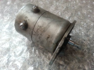
This segment per webmaster. Pictured at right, also seen in Figure 12, is a Delco Remy Overdrive Solenoid part # 118155. This solenoid is a 6 volt application, and has not been made by Delco Remy for over 50 years. The solenoid has two coils inside, a high current coil to throw it and low current coil to hold it. It will be the coils or contact points that burn out on this unit. I've heard that this solenoid has been used on other overdrive applications such as 1955 Willys Bermuda with a Super Hurricane I-6 flat head and Borg Warner 3 speed manual transmission that had an overdrive unit of R10B-1H. The Borg-Warner overdrive was originally designed for two wheel drive applications. The Borg-Warner unit was a forerunner of the Warn overdrive. |
Overdrive Solenoid
 |
What's the difference between the regular 3 speed Hudson manual transmission and the overdrive version? Are they the same except one has an overdrive mechanism installed? Or are they structurally different transmissions?
The overdrive (or fourth gear) is in a separate mechanism behind the 3-speed gearbox. From the outside, it's as simple as an OD unit bolted on instead of the normal tailpiece. Open things up and it's a different story. You have to have the overdrive transmission. You can't just bolt the overdrive unit to the standard three speed.
However, the electric parts are in the OD unit, which is in the tailpiece. For example, a '54 3 speed that is a R type tranny can have OD added on. Even the W type transmissions can add OD, but you'll have to look at the manual and the Hudson parts book to give you the parts you need to change out. For example, you need to mod the shifter forks for the OD lockout. Put a little work into what you have or find a complete transmission and OD.
I have a '52 308 with the single lever three speed, which I believe is the original transmission in my '46 truck. To keep the single lever column shift, what would I need to get for an OD setup?
Here's an incomplete list of things to get you started:
- Hudson 3 speed O/D transmission (single lever, pre-1952)
- Shorter driveshaft (or modify the one you currently have)
- OD Relay
- OD Relay wiring harness
- OD shift cable
- OD transmission support bracket (may not be necessary)
- Before starting, visit: OD Transmission Swap
- Before starting, view: Overdrive Transmission Wiring Diagram
Probably more, but this gives you an idea and a 'start'.
I'm upgrading my Jet from a 6-volt to a 12-volt system? Do I need to make any changes with my overdrive?
The important thing to remember when upgrading from 6-volts to 12-volts is… the relay kickdown switch, and governor will all work fine on 12-volts. The one thing that have to be changed is the 6-volt solenoid, which must be replaced with a 12-volt solenoid. What if I just run the 6-volt Solenoid on 12-volts? All will be fine for about an hour until the holding coils and contact points overheat and burn out. Then you have just ruined your expensive, and hard to find overdrive solenoid. What Will Interchange? Most all of the 6-volt overdrive solenoids can be replaced with a 12-volt solenoid of the same type. For example, a 1950 Ford 6-Volt Solenoid can be replaced with a solenoid from a 1956 and newer 12-volt overdrive transmission. Be sure to compare the shaft lengths of your original 6-volt solenoid with the replacement 12-volt solenoid. Most all 6-volt and 12-volt solenoids used the same shaft length. A few known exceptions include Lincolns, and Packard’s of the late 40's and early 50's, along with some Chevrolet truck applications from the late 50's and early 60's. Also most all convertibles and station wagons used the longer shaft solenoids because of the extra cross member in the frame. Can I just install a Voltage Reducer? NO! There are two different sets of contact points inside of an overdrive solenoid, along with two different sizes of wire windings. The heavy windings are what "pull" the overdrive in gear. Once the overdrive is engaged, the " holding coils " take over and hold the overdrive engaged. One single voltage reducer cannot control two different amperage loads. - Courtesy Fifth Avenue
|
Borg-Warner Overdrive Manual - Click here for companion manuals!
Herm The Overdrive Guy - Click here to view available Electrical Components
|
OverDrive Kick Down Switch (Located Under Gas Pedal):
The Jeepster Man - Phone: 732-458-3966 -
Item # 649790 $19.00
NAPA: Part number is OD6284. They're special order from Balkamp. The lugs are not Hudson lugs, so you'll have to do some modification, but they'll work. Price runs somewhere around $28 or so. (Item may be listed under '57 Ford switches.)
|

|
|
|
|
Courtesy HET JetSet- All Rights Reserved.
|
|