Hudson Jet |  |
DISCLAIMER: Unless otherwise noted, service information has been provided by an edition of the Mechanical Procedures Manual for Jet models. The data from the Manual includes information covering specifications, adjustments and detailed operation involved in maintenance and repair procedures. After market updates from Hudson Service Merchandisers and other sources have been added as well and are credited in italics. HudsonJet.net provides this reference as a courtesy and is not responsible for any work done using Hudson Motor Car Company's publications or other sources provided on this site. |
|
ENGINE - GENERAL
Arrangement
No. Cylinders
Compression Pressure
Firing Order
Serial No. Location
Bore
Stroke
Piston Displacement
Horsepower - Taxable
Horsepower - Actual
torque
CRANKSHAFT
Drive
Bearings
Type
No.
1.
2.
3.
4.
Radial Clearance
End Play
Timing Marks
Timing Chain
Timing Chain Width
Camshaft Sprocket
Cranksahft Sprocket
CRANKSHAFT
No.
1.
2.
3.
4.
MAIN BEARING SIZE
1.
2.
3.
4.
Diametral Clearance
Adjusting Shims
Crankpins
End Play
Thrust |
L Head
6
100 lbs. minimum
1-5-3-6-2-4
Right Hand Front of Block
3"
4-3/4"
202 Cu. In.
21.6
104
158 ft. lbs @ 1400 R.P.M.
Silent-Chain
4
Interchangeable - Steel Back Babbitt
Diameter x Length
2.3 75" x 1"
1.997" x 11/16"
1.965" x 11/16"
1.497" x 1-1/8"
.0005" to .0015"
.003" to .005"
On Sprocket and Chain
60 Links 3/8" Pitch
1"
42 Teeth
21 Teeth
Diameter Journal Length
2.4988" to 2.4998" 1.530"
2.4988" to 2.4998" 1.500"
2.4988" to 2.4998" 1.500"
2.4988" to 2.4998" 1.750"
2.5006" to 2.5010" x 1.312"
2.5006" to 2.5010" x 1.250"
2.5006" to 2.5010" x 1.494"
2.5006" to 2.5010" x 1.500"
.0005" to .0015"
None
1.937" to 1.938" x 1.125"
.003" to .009"
On No. 3 Bearing |
|
CONNECTING RODS
Material
Weight
Length - Center to Center
Bearing - Lower End
Type
Diameter & Length
End Play
Diametral Clearance
Shims
Bushing - Upper End:
Material
Diameter & Lenth
Diametral Clearance
PISTON
Type
Material
Weight
Length (Overall)
Length - Pin Center to Top
Piston Clearance
Ring Groove Depth
PISTON PIN
Type
Length
Diameter
Fit in Piston
Fit in Rod
PISTON RINGS
Material
Compression Rings
Width
Oil Rings
Width - Upper
Width - Lower
Gap Clearance
LUBRICATION
Engine Lubricating Method
Normal Pressure
Oil Pump Type
Oil Pump Drive
Oil Capacity |
Forged Steel
26 ozs.
8.183" to 8.193"
Precision Insert Removable
Steel Back Babbitt
1.9375" x .962"
.007" to .013"
.0005" to .0015"
None
Steel Back Babbitt
.8465" x .870"
0" to .0003"
Cam Ground
Aluminum Alloy
10-1/4 oz.
3.1875"
1.6875"
.0015" to .002"
.148"
Floating
2.4375"
.7497" to .750"
.000" to .0003"
Hand Push Fit at 70° F.
Cast Iron
Two (pinned
5/64"
Two (Pinned)
3/16"
5/32"
.004" to .009"
Pressure
40 lbs. @ 30 M.P.H.
Rotor
Worm on Camshaft
5-1/2 qts. Total
5 qts. refill |
|
INTAKE VALVES
Angle of Seat
Head Outside Diameter
Port Diameter
Lift
Length
Stem Diamter
Stem to Guide Clearance
Operating Clearance - Hot
Inserts
EXHAUST VALVES
Angle of Seat
Head Outside Diamter
Port Diamter
Lift
Length
Stem Diamer
Stem To Guide Clearance
Operating Clearance - Hot
Valve Angle
Inserts
|
45°
1.5000"
1.418"
.356"
5.045"
.3412" to .3422"
.0015" to .0025"
.010"
None
45°
1.395"
1.315"
.356"
5.022"
.3402" to .3412"
.003" to .004"
.012"
7°
None |
TORQUE SPECIFICATIONS - ENGINE
Click here to view and print your own copy of a Torque Chart
that includes torque specifications for the engine! |
VALVE GUIDES
Type
Length:
Intake
Exhaust
Inside Diameter
VALVE SPRINGS
Free Length
With Valve Closed
With Valve Open
Total Coils
Spring Pressure:
Closed
Open
VALVE TAPPETS
Type
Guides
Guide Size
Tappet Size
Fitting Clearance
Length
VALVE TIMING
Inlet Opens
Inlet Closes
Exhaust Opens
Exhaust Closes
Timing Marks |
Removable
2-5/8"
2-5/8"
.3435"
2-3/16"
1.953"
1.607"
8-1/2
40-48 lbs.
116-124 lbs.
Mushroom
Integral with Block
.6245" to .625"
.6325" to .62375"
.00075" to .00175"
2.310"
26.8° BTC
99.7° ABC
64.9° BBC
45.7° ATC
On Vibration Dampener |
|
ENGINE NUMBER
Stamped vertically, reading downward, on the front face of the cylinder block at the top right corner. Engine number is the same as the car number.
ENGINE COLOR
1953 Jet engines were gold. The red engine paint did not show up until 1954 when all engines (202, 232, 262 & 308) were painted red. The correct color is Duplicolor Ford Red Number DE1605 Engine Enamel. A lot of the JC Whitney engines were painted blue. (JC Whitney took all of the surplus factory engines and sold them through their catalog.)
The Hudson Jet, Super Jet, and JetLiner engines are of the "L" head design.
Crankcase and cylinder block are integral, made of chrome alloy iron to provide maximum strength with minimum cylinder wear and weight.
The engine is cushioned against shock and vibration by rubber mountings at three points in cars equipped with standard synchromesh transmissions. One cushion is mounted on the frame side rail at each side of the engine front support plate. The rear of the engine assembly is supported on the No. 3 frame crossmember, the cushion being attached to the under side of teh clutch bell housing. Models equipped with Hydra-Matic transmissions have four rubber engine mountings, one at each side of the transmission supporting the engine at the rear at the No. 3 crossmember. Front engine mountings are identical for both types of transmissions.
A fully counter balanced crankshaft of forged alloy steel is balanced statically and dynamically. Four precision insert type steel back babbitt main bearings support the shaft. Main bearing inserts of several undersize dimensions are available for service requirements. (See Parts Book) Crankshaft end thrust is taken at the No. 3 main bearing.
Connecting rods have replaceable precision insert steel back babbitt bearing shells which are interchangeable.
Aluminum alloy cam ground pistons are provided. Four piston rings are utilized on each piston, steel stake pinned at the ring gaps to prevent ring rotation in the ring grooves.
Piston pins are of the full floating type held in position with steel lock rings fitted into grooves machined near each end of the piston pin bore. Piston pins operate in steel backed bronze bushings pressed in the upper ends of the rods.
The camshaft is made of especially heat treated alloy iron mounted in four steel back babbitt bearings. A Morse chain and sprockets are utilized to drive camshaft.
Mushroom type rotating valve tappets are used. The tappets are fitted directly in the crankcase and may be removed from the bottom of the crankcase after removal of the oil pan and camshaft.
Valves seat directly in the engine block with no valve seat inserts required. The exhaust valves have welded stems with the valve head and upper stem made of Austeneetic Alloy steel to provide maximum heat transfer from the exhaust valve. Removable valve guides are provided for both intake and exhaust valves.
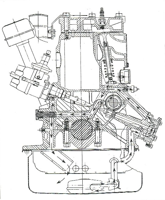
Engine lubrication is provided by pressure to friction surfaces of the engine, Fugre 4. A positive rotor type oil pump is mounted on the right side of the cylinder block. The pump is driven by a worm gear integral with the camshaft.
Oil is drawn through a floating oil screen in the oil pan and the intake pipe to the pump. From the pump, oil under pressure is forced up into the horizontal oil gallery. From the oil gallery, oil is distributed to valve tappets and camshaft bearings. Circulation is also provided through oil laterals to engine main bearings and through holes in the crankshaft to the connecting rod bearings which also provide cylinder wall lubrication. The oil check valve located in the crankcase on the left side regulates oil pressure.
NOTE: Normal oil pressure is 40 pounds at 30 M.P.H.
An oil pressure switch assembly is used in conjunction with the rotor type pressure pump. The function of the pressure switch is to indicate by means of an instrument panel light when there is no oil pressure.
The unit consists of a spring loaded diaphragm and a set of electrical contact points normally closed when the engine is no operating. The closed contact completes a ground connection to the instrument panel lighting the lamp. When the oil pump begins to operate, oil pressure breaks the ground contact, and the lamp goes out.
|
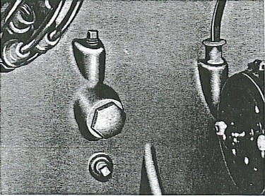
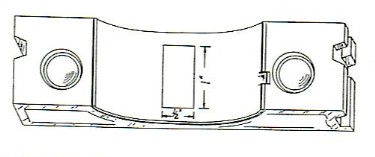
Oil pressure is maintained by a non-adjustable oil check valve consisting of a plunger, spring, plug retainer and plug gasket. The assembly is located in the left side of the crankcase slightly below the distributor. Oil pressure against the end of the plunger and spring forces the plunger off its seat allowing oil to return to the oil pan, Figure 1.
Click here to view article on Oil with ZDDP. |
FIGURE 1
 |
The oil pump is of simple construction and very efficient providing high volume. It is a rotor type pressure pump. Servce is seldom required.
REMOVAL
Care must be excercised to maintain correct engine ignition timing when it is necessary to remove the pump for servicing. The recommended procedure is as follows:
- Lift off the distributor cap and rotate the engine crankshaft until the distributor rotor is in firing position for the number one cylinder. Do not disturb this position of the engine while the oil pump is removed.
- Remove the two oil pump to block attaching screws and remove the oil pump.
|
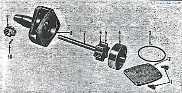
DISASSEMBLY
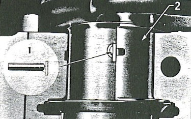
- Remove the cover screws (1), Figure 2, cover (2) and gasket (3).
- Hold hand over cover opening and with the pump upside down, turn shaft until the pump rotor (4) falls out in the hand.
- Drive out straight pin (10) which holds pump drive gear to pump shaft.
- Press shaft (7) out of gear (9) by supporting the oil pump body (8) on the cover face in an arbor press allowing the inner rotor and shaft to clear when pressing the shaft out of hte pump gear.
- Wash all parts in cleaning solvent and dry with compressed air.
|
FIGURE 2
 |
INSPECTION
- Install rotors and shaft in pump body with the inner rotor located so that one lobe of the inner rotor contacts the corresponding notch in the outer rotor. Measure the clearance between the opposite lobe of the inner and outer rotor. This clearnace should be .010" or less. If more that this, replace both rotors and shaft.
- With rotors and shaft assembled in the pump body place a striaght edge across the pump body between the screw holes and using a feeler gauge, measure the clearance between the top of the rotors and the straight edge. This clearance should be .004" or less. If the clearance is greater than this limit, the pump body must be replaced.
- With the outer rotor (4) pressed against one side of the pump body, with a feeler gauge measure the clearnace between the outer rotor and pump body at the opposite side. If this clearance is more than .008", replace the pump body.
- Body cover (2) should be smooth. It should be replaced if scratched, grooved or worn. Lay a straight edge across the inner surface of cover and check with .002" feeler gauge between the cover and straight edge. If the feeler gauge can be inserted, the cover is worn and must be replaced.
ASSEMBLY
- Install the outer rotor (4) in the pump body (8), Figure 2.
- Slide the pump shaft (7) and rotor (5) assembly into the pump body.
- Support oil pump body, shaft and rotors assembly on a clean surface and press pump drive gear (9) on pump shaft (7). End play between the hub of the drive gear and pump body should be .004" to .008".
- Install gear pin and peenover both ends securely.
- After inspecting to see that pump is thoroughly clean, install cover gasket (3) in the recess in the pump body.
- Install cover (2). Tighten cover screws (1) evenly and securely.
|
INSTALLATION
If the engine crankshaft has been rotated inadvertently during the interval the oil pump was out being repaired, ignition timing will be incorrect. The following steps will then be necessary to remedy the improper timing.
- Remove the distributor mounting screw, disconnect the distributor vacuum control tube, disconnect the coil lead wire and remove the distributor.
- Set dampener timing with the No. 1 piston on T.D.C.
- Insert aligning tool J-2794 in the distributor shaft hole with the aligning pin in line with the distributor mounting screw hole, Figure 3.
|
FIGURE 3
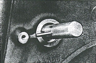 |
NOTE: The slot in the end of the oil pump shaft is machined off center as is the tongue on the end of the distributor shaft, Figure 4.
- Install the oil pump, engaging the oil pump drive gear with the camshaft worm gear teeth. The pump shaft must be aligned to engage the shaft slot with the tongue on the end of the aligning tool. Then push the tool out as the pump is seated against the block mounting face.
- Remove aligning tool J-2794.
- Set distributor in No. 1 firing position and install.
- Install distributor mounting screw, distributor cap, distributor vacuum control tube and connect the coil lead wire.
FIGURE 4
 |
REMOVAL
- Raise car and place stand jacks under the No. 2 frame crossmember.
- Remove the three bolts attaching the center steering arm support bracket to the No. 2 crossmember. This permits the center steering arm and tie rods to drop.
- Remove the two attaching bolts, flywheel dust cover to bell-housing, and remove dust cover.
- Remove oil pan drain plug and drain oil.
- Remove bolts and lockwashers attaching oil pan to cylinder block and remove oil pan.
NOTE: Do not lose the round rubber gasket at the oil outlet tube.
|
INSPECTION
- Remove all traces of old gaskets from the pan and crankcase. Install new gasket, applying a light coat of Hudson Perfec Seal Gasket Paste on both sides of the new gasket.
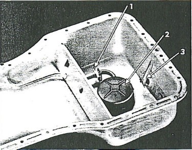
- Remove cotter pin (1) Figure 5, attaching oil pan screen to the outlet pipe. Clean screen throughly or replace.
- Install oil pan screen to oulet pipe. Check to be certain there is no binding action and screen swivels freely.
- Secure ends of cotter pin.
|
FIGURE 5
 |
INSTALLATION
- Install rubber gasket on the outlet tube.
- Install the oil pan to the engine, using two screws on each side until all screws have been started.
- Tighten oil pan screws evenly to 15 to 20 pounds torque.
- Install oil pan drain plug.
- Install flywheel dust cover.
- Install center steering arm support bracket and tighten bolts securely.
- Fill oil pan with 5-½ quarts of motor oil of the recommended viscosity.
as suggested in Hudson Service Merchandiser
Vol. 5, No. 6, June 1953
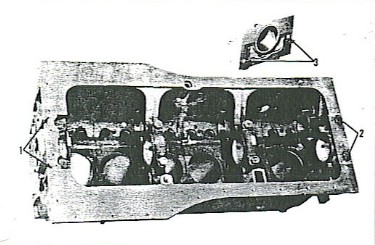
The first operation in the machining of the cylinder block consists of drilling two holes through the flange, to which the oil pan is bolted, one at the right front side, the other at the left rear side of block. These holes serve to located the block in the various fixtures for all machine operations.
The locating hole in the left side is directly behind the starter motor and is in a position that about onehalf of the hole opens into the crankcase. This makes it very important that this hole be plugged to prevent water, dust, mud, etc., from reaching the interior of crankcase.
It is believed that some Jet cylinder blocks, skeleton engines and possibly a few complete engines, may have been shipped that did not have this plug, Part 171091, in position, as is shown in the illustration below.

Make it a point to check all these units, as it is vitally important that this opening be plugged. In addition to possibility of dirt reaching the interior of engine, the oil is likely to be lost very rapidly through this opening. Special Tool J-483 is ideal for making installation of this plug.
- Drain cooling system.
- Loosen carburetor air horn attaching screw and clamp and lift off air cleaner.
- Disconnect and remove vacuum advance control tube.
- Disconnect top radiator hose.
- Disconnect heater hoses (if so equipped).
- Disconnect throttle rod at carburetor.
- Disconnect temperature gauge wire at cylinder head sender unit.
- Disconnect spark plug wires and remove spark plugs.
- Remove cylinder head cap screws and lift off cylinder head.
- Remove temperature gauge sender unit from cylinder head.
INSTALLATION
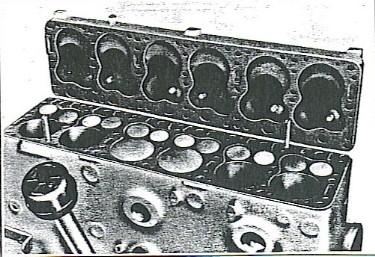
- Make certain cylinder head is free of carbon and dirt. Check cylinder head with a straight edge to detect roughness or warping, expecially in those instances of frequent "blowing" of head gaskets. With a ,010" feeler gauge, check between the straight edge and the machined surface of the cylinder head. If the feeler gauge enters at any point, the head must be remachined or replaced.
- Install new head gasket with lettering on gasket up. (Apply a light coating of "Hudson Perfect Seal Gasket Paste".)
NOTE: Cylinder head and gasket installation can be facilitated by using two J-2969 cylinder head locating studs to align the gasket and head. These studs have a screw driver slot for easy removal after the cylinder head has been aligned, Figure 6 .
|
- Cylinder head cap screws should be tightened to 75-80 foot pounds, (Cold) using a torque wrench and retighten when engine is at normal operating temperature.
FIGURE 6
|
VALVES
as suggested in Hudson Service Merchandiser Vol. 5, No. 8, August 1953
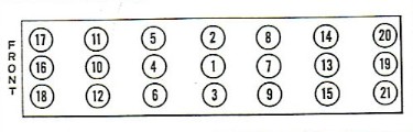
The valve sequence as shown in Figure 6 [at left], Page 27, of the Jet Procedure Manual is not applicable to the Jet Engine.In order to avoid any confusion in this connection, the [below] illustration shows the correct sequence of intake and exhaust valves of the Jet Engine.

|
- Cylinder head cap screws should be tightened in the sequence illustrated in Figure 7.
|
FIGURE 7
|
CAUTION: Always clean out threads incylinder block before installing cylinder head. If threads in the block are corroded or filled with dirt, an incorrect torque wrench reading will be indicated, as a percentage of the torque will be absorbed by the threads. Apply "Hudson Perfect Seal Gasket Paste" to threads to facilitate tightening of the cap screws to the proper tension.
- Remove right front wheel.
- Remove fender side shield.
- Remove valve covers and breather. Adjust tappets as follows:
- Intake .010" hot
- Exhaust .012" hot
VALVE REMOVAL
The engine block is of ahrd chrome alloy iron and the valves seat drectly in the block with no valve seat inserts required. The following procedure is recommended for removing valves:
- Drain cooling system.
- Remove cylinder head. See "Cylinder Head Removal".
- Raise car and remove right front wheel and fender shield with extension.
- Remove front and rear valve covers and crankcase breather tube.
- Compress valve springs and remove spring keepers and retainers (use tool KMO-484 Valve Spring Lifter).
NOTE: Place corks or wood plugs in valve chamber oil return holes to prevent valve locks from dropping through those holes into the oil pan.
- Remove valves from engine and place them in proper sequence in a valve rack to assure their installation on the seats from which they were removed.
- Check all valves and replace those badly burned, warped or cracked.
REFACING VALVES
Remove enough metal to clean up pits and burns. Grind until a clean metal surface is obtained to provide a good seal on the seat. Do not grind to a knife edge at the top of the valve. At least 1/16" of metal should remain, measured from the upper edge of the valve seat to the top of the valve shown at (D), Figure 9. If this thickness of metal does not remain after grinding, replace the valve.
REFACING VALVE SEATS
Before refacing valve seats, it is necessary to clean all carbon and varnish from valve guides. Cleaning can be quickly accomplished usinga KMO-122 Valve Guide Cleaner Metal Brush mounted in a small electric drill. Place a cloth below the valve guides in the valve chamber to catch dirt and excess thinner and prevent it from dropping into the oil pan.
The valve guides must also be checked for excessive wear before attempting to reface the valve seats. Excessive valve guide wear can usually be detected by an oily deposit on the under side of the intake valve heads or in the intake valve ports.
STANDARD CLEARNACES
VALVE GUIDES & VALVE STEMS
| INTAKE | EXHAUST |
| Valve Guide Bore | .3437 | .3437 | When valve guides must be replaced, they may be removed by driving them out with J-267 valve guide remover after taking out tappet adjusting screws. |
| Valve Stem Diameter | .3417 | .3407 |
| Clearance | .002 | .003 |
|
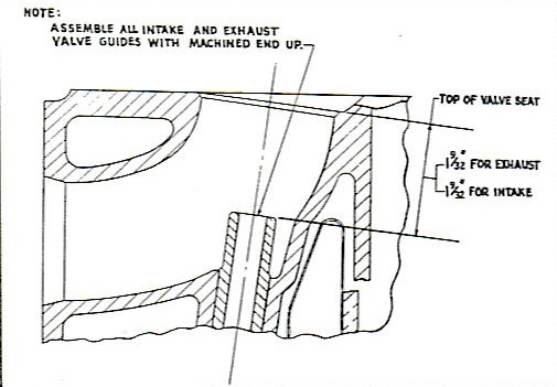
Valve guides can be properly installed with the J-883-A Valve Guide Installer using pilot J-883-10. The installer consists of the driven handle, stop collar and a pilot calibrated to limit the depth to which the guides are driven. The valve guides are inserted to a depth of 1-9/32" from the top of the valve seat to the top of the guides for both intake and exhaust valve guides. (See Figure 8.
|
FIGURE 8
|
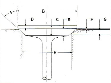
INTAKE
A - 45°
B - 1.831"
C - .1135"
D - .0495"
E - .083"
F - .016"
G - .054"
H - 1-11/16" | EXHAUST
45°
1.561"
.1525"
.0496
.103"
.008"
.075"
1-3/8" |
|
FIGURE 9
|
Before starting to reface the valve seat, be sure that the stone is clean and true. Touch the valve seat lightly with the stone to avoid chatter of the grinder. Grind seat until all pits are removed and the seat is clean.
Seats should be held to a width of from 1/16" to 3/32" inch. When the seat is too wide, difficulty is encountered trying to obtain a good seal. If a wide seat is found, grind the edge with a 20° stone until proper seat width is obtained. If necessary, an additional cut can be taken at the port end with a 75° stone if the valve does not contact the valve seat within the guage line limits. (See Figure 9.)
Valve tappets are of the mushroom rotating type with self-locking tappet adjusting screws.
The valve tappets must be removed from the bottom of the cylinder block. To accomplish this, the oil pan, and camshaft must be removed, while holding the valves wide open with J-1612-3 tappet and valve holders.
Valve tappets should be carefully inspected for pitting and scratches on the mushroom faces that might damage the cam lobes. Replace any tappets that are pitted or scratched.
If the valve tappet guides are worn excessively, the tappets should be removed, the guides reamed and oversize tappets installed. Tappets avaiable are standard, .002", .004" and .010" oversizes.
REMOVAL
Pistons and connecting rods must be removed through the top of the cylinder block. The oil pan and cylinder head must, therefore, be removed prior to srevicing pistons and connectings rods.
NOTE: Before rods and pistons are removed, the ridge must be removed from the upper cylinder walls with a Ridge Reamer. This is necessary to prevent cracked or broken piston lands or piston rings.
PISTON & SIZE CODE
A code letter is stamped on the cylinder block along the lower face of the valve chamber to shw the original size of each cylinder.
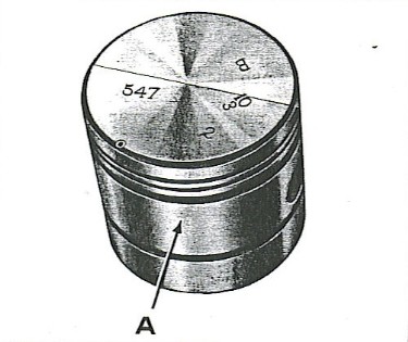
A code letter and the piston weight in ounces and quarter ounces is stamped on the head of each piston. In addition, each piston is also stamped during original factory installation with the block number and the number of the cylinder in which each piston is fitted.
|
EXAMPLE: The piston from the No. 2 cylinder of a certain engine is marked as shown in Figure 10. The number "547" stamped on the piston is for identifying this piston as one of a matched set to be installed in the No. 2 cylinder of the engine block bearing the same number. The number is stamped on the front of the cylinder block to the right of the water pump. The mark "B" is the code letter stamped on both the piston and the lower face of the valve chamber. By referring to the Code Marking Chart, in the next column, the definite size of the piston and cylinder bore can be determined. The "10"/3 stamped on the top of this piston indicates that the weight of this piston is 10-¾ ounces. Similary, a piston stamped "10"/1 would indicate a piston weight of 10-¼ ounces. The number "2" is the number of the cylinder in which the piston is to be installed.
When a piston is being replaced, it should be of the same weight as the one removed. A complete set of new pistons should always be of the same weight because unequal piston weight can cause unbalance and rough engine operation.
|
FIGURE 10
|
NOTE: Piston sizes shown in the chart are the major diameters at the top of the piston skirt at "A", Figure 10, just below the chamfer under the No. 3 ring groove.
The difference between the cylinder size shown on the chart and the piston size shown gives the recommended piston and cylinder clearance.
KEY TO CODE MARKINGS - PISTON, CYLINDER, RING SIZES
| (Ring Oversizes Apply Only to Production Type Rings) |
| CYLINDER | PISTON | PISTON RING |
| Size | Code | Code | Size | Size |
3.005
3.0015
3.0025
3.0045
3.0055
3.0075
3.0105
3.0115
3.0125
3.0145
3.0205
3.0215
3.0225
3.0305
3.032 | B
D
BO
DO
| B
D
F
J
L
P
BO
DO
FO
LO
BB
DD
FF
BOOO
EOOO | 2.9985
2.9995
3.0005
3.0025
3.0035
3.0055
3.0085
3.0095
3.010
3.013
3.0185
3.0195
3.0205
3.0285
3.030 | 3.000
3.000
3.000
3.003
3.005
3.005
3.010
3.010
3.010
3.015
3.020
3.020
3.020
3.030
3.030 |
Cylinder bore sizes from standard to .030" oversize are given in this chart and the recommended piston and ring sizes for each bore size.
It is always advisable to hone the cylinder to the smallest dimension for which a given ring is recommended. Ring oversizes shown in the table are available only in production type rings. Service piston rings are available in .003", .005", .010", .015", .020", and .030" oversize for this engine.
as suggested in Hudson Service Merchandiser Vol. 5, No. 8, August 1953
JET RINGS:
Compression and oil rings used in the Jet Engines in production are of the following sizes: standard and 10 thousandths oversize. These are shown listed on Page 63 of the Group Parts Catalog.
Both the upper and lower compression rings have a 50 degree bevel on the inside, and must be installed on the piston with this bevel TOWARD THE TOP. The object of this is to cause a slight twist in the ring when closed in a cylinder bore and produce a line contact between the cylinder wall at the lower edge of the ring. This effects a highly efficient seal.
The upper compression ring may be identified by the fact that it is chrome plated on the outer diameter. Chrome plating not only reduces friction, increases efficiency and affords greater protection to those rings, but also prolongs their life.
The lower compression ring has a Granoseal process coating. Both rings are of the same width, 5/64 of one inch, and the tension when closed to cylinder size is 7¼ to 11¼ pounds.
The upper oil ring is Granoseal processed and 3/16 of an inch wide. The lower oil ring is a plain turned ring, 5/32 of an inch wide. The tension of both rings when closed to cylinder size is 8 to 12 pounds.
4-C AND 5-C RINGS:
The compression and oil rings used in the 4-C and 5-C Engines in production are standard and 10 thousandths oversize, as are shown on Page 63 of the 1953 Group Parts Catalog.
The upper and lower compression rings are the same. The cylinder contact surface is tin or Cadium plated. Both rings are 5/64 of an inch in width. The closing pressure is 8½ to 12½ pounds.
The upper oil ring is .1865/.186 wide and is tin plated. The lower ring is .155/.154 wide and is Granoseal treated. The closing pressure of the upper oil ring is 11 to 15 pounds, that of the lower is 6 to 10 pounds.
7-C RINGS:
Four rings -two compression and two oil rings- are carried on the pistons of the 7-C Engine. The production sizes are standard and 10 thousandths oversize. The upper compression ring has a bevel cut on the inside and must be installed with this bevel TO THE TOP of piston. The lower compression ring has a .0005 taper on the outer face and has the word TOP stamped on the ring land to designate its installed position.
The upper compression ring is 5/64 of an inch wide and is chrome plated on the outer diameter. The closing pressure is 9½ to 13½ pounds. The lower compression ring, also 5/64 of an inch in width, is Cadium or tin plated, having a closing pressure of 10 to 14 pounds.
The upper oil ring is 3/16 of an inch wide, tin plated on the outer diameter, and the closing pressure is 11 to 15 pounds. The lower oil ring is .154/.155 wide, is Granoseal processed and has a closing pressure of 6 to 10 pounds.
 The gap clearance of all rings is.004 to .009. Rings must fit free in ring groove with no tendency to bind. When installing rings on pistons, BE SURE that successive rings are assembled in the grooves with their gap on opposite sides of center line of the retaining pin. The gap clearance of all rings is.004 to .009. Rings must fit free in ring groove with no tendency to bind. When installing rings on pistons, BE SURE that successive rings are assembled in the grooves with their gap on opposite sides of center line of the retaining pin.
Should the top ring be installed with the short half of the notch on the right side of the pin, the second rings must then be installed withthe short half on the left side of the pin and the third in the same relative position as the first. Note illustration above.
PISTON RINGS - SERVICE
For Service replacement, the following piston rings sets are available: Sealed Power Kromex, Steel Segment Type and Cast Iron Type. Ring sizes are standard and .020 oversize for the 202, 232, 262 and 308 Cubic Inch Engines. For the 254 Cubic Inch Engine (1946-1952, 8 Cyl.), standard, .010 and .020 oversize.
Kromex is a premium replacement ring set and is specially designed for installation without the necessity of reconditioning cylinders. The compression rings seat to cylinders rapidly due to a slight taper on the outer face. The top compression ring is of chrome bonded to the face of the ring to double resistance to heat, corrosion, friction, scuffing and border-line lubrication. A specially designed spring behind the upper oil ring not only makes for even distribution of wall pressure, but also effects immediate control of oil and prevents blocking of the oil return holes in piston. The sides of all rings are Granosealed to assure proper lubrication.
Steel Segment Type oil ring is also highly satisfactory for use without reconditioning the cylinders, where the original rings are worn and there is some taper or out of round in cylinders. Both upper compression rings are tapered for rapid seating. The upper compression ring is supplemented by steel segments, both at the upper and lower ring land. The specially designed Full Flow inner spring is also used with this ring.
 Cast Iron Type ring set is similar to the original production rings. It is recommended that the cylinder walls be trued-up when this set is used for replacement. All rings are Granoseal treated. Cast Iron Type ring set is similar to the original production rings. It is recommended that the cylinder walls be trued-up when this set is used for replacement. All rings are Granoseal treated.
The upper ring of each of the above replacement ring sets has a bevel cut-off on the inner face and the ring must be installed with this bevel TOWARD THE TOP. All second compression rings are tapered, the rings having the mark TOP on the ring land. An expander spring is used behind the second compression ring and the upper oil ring of all three replacement ring sets.
To avoid damaging piston rings or pistons use KMO-297 Piston Ring Remover and Installer of the correct size.
Complete instructions applying to the installation of various oversize service piston ring sets are contained on each ring wrapper or on a sheet packed within the box.
Pistons are cam ground to eliptical shape. Under normal operating temperatures,expansion of the piston bosses forces the piston to assume a circular form.
The pistons are also tapered, measuring approximately .0007" to .0012" larger at the bottom of the piston skirt than at the thrust face.
Cam grinding makes careful fitting of the piston in the cylinder bore necessary. A .002" feeler gauge ½" wide, extending the full length of piston travel, is inserted between the cylinder bore and the thrust face of the piston directly opposite the valve mechanism. The feeler gauge should be moved by a pull of from 3 to 4 pounds. Use Tool J-888 to measure the pull. A variation of .001" will change the pull on the feeler gauge only a few pounds. Use of the scale will eliminate guesswork.
NOTE: Check the piston fit in the cylinder bore when both the cylinder block and piston are at room temperature (70° F). Always be certain that the ridge at the top of the cylinder has been removed before attempting to fit pistons.
CYLINDER BORING
Before fitting pistons, examine the cylinder walls for scratches, scores and wear. Cylinders should be checked for taper and out of round with a Cylinder Checking Gauge KMO-913. It is recommended that the cylinder bores be reconditioned when the taper exceeds .020" and out of round is greater than .005".
Honing will remove cylinder wall scratches and scores up to .005" metal depth. An experienced operator can remove metal up to .010" to .015" depth. Reboring is recommended only where cylinders are so badly scored, worn, tapers or out of round that honing will not provide a satisfactory finish.
After boring operations have been completed, the cylinder walls should be polished with crocus cloth dipped in kerosene. If the cylinder walls have been either honed or rebored, they should be thoroughly washed with soap and water, using a brush to remove all traces of grit, chips and abrasive materials. Otherwise, extremely rapid wear of new parts will result.
Piston pins are of the full floating design. The pin rotates in the connecting rod bushing with sufficient movement in the piston to equalize wear. The piston pin hole is diamond bored for close fitting of the pin.
The piston pin and connecting rod bushing should be replaced if necessary. Select the proper size pin to fit the piston and ream the connecting rod bushing to size.
To remove the piston pin, remove the piston pin lock rings. heat the piston and connecting rod assembly to 200°F. in water or in an electric furnace. (Never heat the pisto with a blow torch as this may distort the piston.) Push the piston pin out with hand pressure, using Tool J-2948 Piston Pin Remover. If the pin cannot be removed by hand pressure, tap lightly on the tool with a hammer while holding the piston in one hand. Do not hold the piston solidly during this operaton as distortion and misalignment could result.
Piston pins should be a tight hand push fit in the piston bores with the pistons heated to 200°F. Piston pins are available for service in the oversizes shown and are identified with a color code by a spot of paint on the end of each pin. Following is a chart showing pin sizes, color code and bushing diameters after reaming:
| SIZE | PISTON PIN
DIAMETER | COLOR | BUSHING
DIAMETER |
Standard
.001"
.002
.005"
.010"
.015"
.020" | .7499
.7509
.7519
.7549
.7599
.7649
.7699 | None
Yellow
Orange
White
Blue
Green
Brown | .7502
.7512
.7522
.7552
.7602
.7652
.7702 |
If the pin selected cannot be installed with hand pressure, enlarge the hole with an expansion reamer or a hone. Take very light cuts until the pin can be fitted to the piston as outlined above.
|
Connecting rod bushings are steel back bronze burnished in place in the connecting rod bore and diamond bored to very close tolerance.
REMOVAL AND REPLACEMENT
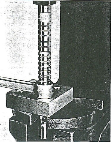
Press out the old bushing by supporting the bushed end of the connecting rod on Bushing Burnisher Block J-2951 and press the bushing out, using Bushing Remover and Replacer J-2948. Press the new bushing in place in the connecting rod bore. Be certain the oil hole in the bushing is aligned with the oil hole in the connecting rod bore. Burnish the bushing in place, using burnishing tool J-2949, (Figure 11).
NOTE: This operation swages or expands the bushing in the rod bore. This prevents the bushing from working out of the rod.
|
FIGURE 11
|
The bushing should be reamed .003" larger than the piston pin diameter. To ream, remove the connecting rod bearing cap and mount on Aligning Fixture J-874-H Arbor (1.9375 diameter). (Tighten rod on carbor and lock in position by tightening the arbor lock screw located on the side of the fixture.)
Mount the reamer pilot bushing in the face plate bore on the upper end of the fixture and lock the lower arbor in place with the locking handle. Insert the reamer through the connecting rod bushing and into the pilot bushing and perform the reaming operation, (Figure 12).
|
FIGURE 12
|
CONNECTING RODS
Connecting rods are drop forged heat treated steel with an I-beam section. An oil metering hole is provided in the upper half of the connecting rod bearing to provide an oil spray for cylinder wall lubrication. This oil metering hole indexes with the hole drilled in the crankshaft as the piston aproaches top dead center on each piston stroke. This sprays additional oil on the exposed cylinder wall.
Connecting rods have steel backed babbitt lined bearing inserts, with upper and lower halves interchangeable in all rods. Bearing halves interchangeable in all rods. Bearing halves are held in position by the extruded portion of the bearing shell fitted into ntoches machined in the rod and cap.
Replacement bearings require no reaming or fitting. Connecting rods are interchangeable. When replacing rods, the weight of new rods should not vary more than ¼ ounce in any one group of rods.
NOTE: New bearing inserts should be installed only in pairs. Never file bearing caps to provide proper clearance when installing new bearings.
Before installing new connecting rod bearings, the crankpin journals should be checked for war, out of round should not exceed .0015" and taper no mroe than .001". Measure journals vertically and horizontally with a micrometer and check at both ends for taper.
Diametral clearance of the connecting rod bearing should be .0005" to .0015" and the rod end play .007" to .013". The clearance can be checked either by the plastigage or shim method.
PLASTIGAGE METHOD
- Remove the bearing caps one at a time and insert a length of plastigage slightly shorter than the cap width.
- Install the bearing cap with a new standard insert and tighten to 40 to 45 foot pounds torque. Do not rotate the crankshaft while the plastigage is in place.
- Remove the bearing cap and check the width of the flattened plastigage. If the width is not over .00225", a standard bearing should be installed.
SHIM METHOD
- Place brass shim stock .0015" thick, 1/2" wide by 7/8" long in the bearig cap with a new standard bearing in place.
- Tighten the bearing cap to 40 to 45 foot pounds torque.
- Try to move the rod endwise by hand, then tap lightly with a hammer. If the rod will not move by hand, but moved when tapped with the hammer, a standard bearing should be used. If the rod can be moved by hand, install an undersize bearing.
Bearing shell thickness, crankpin diameters and connecting rod bores are given for standard and various undersize bearings.
BEARING
SIZE | SHELL
THICKNESS | CRANKPIN DIAMETERS | CONNECTING
ROD BORES |
Standard
.005" U.S.
.002"U.S.
.010" U.S.
.012" U.S.
|
.0622"
.0619"
.0627"
.0624"
.0632"
.0629"
.0672"
.0669"
.0682"
.0679" |
1.938"
1.937"
1.9376"
1.9366"
1.936"
1.935"
1.928"
1.927"
1.926"
1.925" |
2.0630"
2.06325"
2.0630"
2.0625"
2.0630"
2.0625"
2.0630"
2.0625"
2.0630"
2.0625" |
After tightening the connecting rod bolt nuts to the proper torque, install Palnuts snug against the bolt nuts. Then tighten the Palnuts 1/4 to 1/3 more to lock the Palnuts in position. New Palnuts should always be used when rods are reassembled.
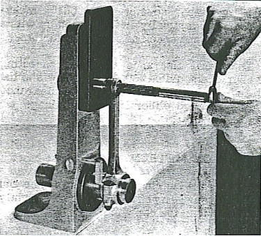
PIN TO ROD ALIGNMENT
- Remove connecting rod bearing shells and mount rod on the arbor, (Figure 13).
- Place the "V" block against the piston pin. The amount of misalignment will be shown by the clearance between the pins on the "V" block and the face plate.
If the two top pins contact against the face plate and the two bottom pins fail to contact the face plate, the rod is cocked or bent. The same condition exists if the bottom pins contact the face plate and the upper pins show a clearance. When the pins in a horizontal plane ocntact the face plate and the other two do not, the connecting rod is twisted.
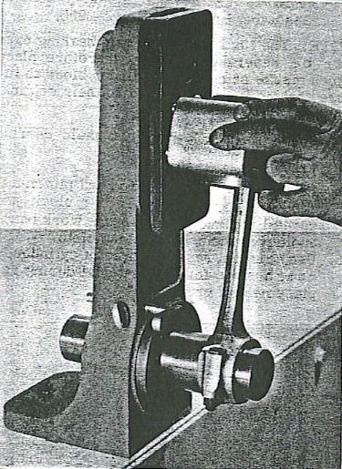
ALIGNING ROD WITH PISTON
A quick check of a piston and connecting rod assembly can be made for both twist and bend without desassembling the piston from the connecting rod.
- Mount the connecting rod and piston assembly on the alignment fixture and set the piston in line with the connecting rod.
- Place the "V" block on the piston skirt. If both pins on the "V" block contact the face plate, then the rod is straight.
- With the "V" block on the piston skirt and the pins against the face plate, rotate the piston first in one direction and then in the other. If the pins on the "V" block contact the face plate at all points, the connecting rod is not twisted. If one pin leaves the face plate while being rotated in one direction and the other while being rotated in the opposite direction, the rod is twisted.
|
FIGURE 13
|
To straighten a bent or twisted rod, use two Bending Bars HM-3-R, one to hold the rod and the other to bend or twist the rod into proper alignment. Always bend beyond the true alignment position and then bend back straight to relieve the stress that results from the bending operation. If the stress is not relieved, the rod will not hold its alignment after installation in the engine.
The crankshaft can be removed from the engine without removing the engine from the car. However, it is more practical to remove the engine when replacing the crankshaft.
NOTE: After removing the transmission the engine can be removed as one unit with the electrical units and carburetor attached.
- Remove the two hood hinge bolts from each side at the rear of the hood.
- Lift and remove hood.
- Drain cooling system, open drain at bottom right side of radiator. Remove drain plug from left rear side of the engine.
- Disconnect the throttle linkage.
- Disconnect the fuel line at the junction of the fuel pump flexible hose and steel gas line.
- Remove the bolts from the exhaust pipe to the exhaust manifold flange.
- Remove the radiator hoses.
- Disconnect the remote control rods at the transmission.
- Disocnnect the wire at the starter motor and remove the cable from the battery.
- Disconnect the water temperature gauge wire from the side of the cylinder head.
- Disconnect the oil gauge light wire.
- Disconnect the vacuum tube from the windshield wiper motor.
- Remove the two generator lead wires.
- Disconnect the primary coil wire.
- Remove slotted head screw holding the breather tube to the rear tappet cover.
- Remove the bolt from the bracket attching the breather to the engine end plate.,/li>
- Remove the nine hexagon head self-tapping screws holding the hood lock lower support panel to the fender tie panel and remove the support panel.
- Remove the four hex bolts attaching the radiator to the channel, also remove the four nuts located inside the radiator channel. Lift the radiator up and out of the channel.
- Remove the two front engine mounting bolt nuts.
- Drain engine oil.
- Disconnect the rear end of the propeller shaft at the rear axle companion flange, lower shaft and pull rearward out of transmission. Remove transmission.
- Remove the nuts from the clutch throwout lever release rod.
- Attach motor lift bracket and raise engine up and out of chassis, and place engine up and out of chassis, and place engine on bench or motor rebuilding stand.
|
CRANKSHAFT REMOVAL
- Remove the flywheel housing dust cover.
- Remove the clutch. See "Clutch Removal", and remove the flywheel.
- Remove the oil pan.
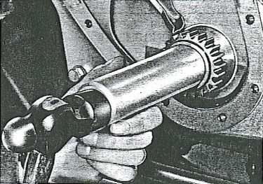
- Remove the vibration dampener cap screw, lock, and remove the vibration dampener. Using Puller J-5371, Figure 14. See "Vibration Dampener Removal".
Do not hammer on dampener to remove.
- Remove gear case cover.
- Remove camshaft gear and timing chain.
|
FIGURE 14
|
- Using Puller J-471, remove the crankshaft gear (Figure 15).
- Remove connecting rod palnuts, attaching nuts and remove connecting rod caps. Be sure caps are installed on connecting rods in the same order as removal.
- Remove front and rear main bearing caps using Bearing Puller J-2955.
NOTE: The No. 2 and No. 3 main bearing caps can be reversed in error, therefore place punch marks on caps and cylinder block to insure that caps are returned to their original position.
- Remove No. 2 and No. 3 main bearing caps.
- Lift out the crankshaft.
- Remove the connecting rod and piston assemblies from the cylinder block and carefully place them on the work bench and cover them with a clean cloth.
- use clean rags in bores and cylinder to catch any foreign material during replacement of crankshaft.
|
FIGURE 15
|
Before installing the crankshaft and bearings, the crankshaft should be checked for wear, out of round and taper. The limit on out of round and taper of main bearing journals should be no greater than .001". Check with micrometers horizontally and vertically. The recommended main bearing clearance is .0005" to .0015". Proper clearance can be checked by wither the plastigage or shim methods.
|
To check clearance with shim stock, remove one bearing cap at a time. Install a piece of brass shim stock, .002" thich by ½" wide by 1" in length crosswise in the bearing. Oil the shim stock freely to avoid bearing or journal damage. Tighten the bearing cap bolts to a torque of 75 to 80 foot pounds. A considerable drag indicates correct clearance. Rotate the crankshaft only ¼ to ½ revolution. If no drag is felt and the crankshaft can be rotated freely be hand, an undersize bearing shell should be installed, Figure 16.
|
FIGURE 16
|
Main bearings are available in .001", .002", .010" and .012" undersizes. Bearing upper and lower halves are interchangeable. Bearing shells are ink stamped on the back with the part number. Bearings should be replaced in pairs; never use a new bearing half with an old bearing half.
Main bearing insert sizes, crankshaft and cap bores are shown in the following table:
BEARING
SIZE | SHELL
THICKNESS | CRANKSHAFT DIAMETERS | CAP BORE
DIAMETERS |
Standard
.001" U.S.
.002"U.S.
.010" U.S.
.012" U.S.
|
.0955"
.0952"
.0960"
.0957"
.0965"
.0962"
.1005"
.1002"
.1015"
.1012" |
2.4998"
2.4988"
2.4998"
2.4988"
2.4978"
2.4973"
2.4898"
2.4893"
2.4878"
2.4873" |
2.692"
2.691"
2.692"
2.691"
2.692"
2.691"
2.692"
2.691"
2.692"
2.691" |
|
Main bearing upper halves can be removed and replaced without removing the crankshaft from the engine. Use tool KMO-734 Bearing Shell Remover and Replacer, Figure 17. Enter tool in crankshaft oil hole with hinged head against the bearing end. Bearing shells are held in position by an extruded end fitting into a machined notch at one end of the main bearing caps and bores. Place the tool at the end of the upper bearing insert oppostie the notch and rotate the crankshaft in a clockwise direction to remove. Turn in a counter-clockwise direction to install new bearing upper halves.
|
FIGURE 17
|
REAR BEARING OIL SEAL
- Remove old seals from crankcase and rear bearign caps and thorughly clean grooves and flanges.
- Using a new seal coat lips of seal and groove with liquid soap and press seal over flange in crankcase and bearing cap.
NOTE: Both halves of seal are identical and must be pressed in place so that bottom of groove in seal contacts the bearing cap and crankcase flange all around: Edges of upper and lower seals may project slightly beyond parting line of cap and crankcase.
- Remove the rags from cylinder bores, oil bores, clean pistons, rings and connecting rods and install in block.
- Place crankshaft in main bearings and install main bearings and bearing caps. Tighten bearing cap bolts to 70-80 ft. lbs.
After installation of new main bearing shells, crankshaft end play must be checked. The shaft thrust limits are .003" to .009". End play can be determined by using a dial indicator.
Move the crankshaft in one direction until the shaft thrust surface contacts against the bearing thrust surface as outlined above.
Mount a dial indicator on the block with the indicator pin against the crankshaft rear flange.
Pry the shaft in the opposite directon to its limit and note the total amount of end play shown on the dial indicator.
|
- Install connecting rods to crankshaft, torque connecting rod bolt nuts to 40-45 foot pounds and install palnuts.
- Install wick packing into the vertical holes (1) and (2), Figure 18, in front and rear caps first, then into the horizontal holes (3) of the front bearing cap.
NOTE: When installing a new packing, use a blunt punch with a diameter slightly smaller than the packging groove. Punch end should be not shorter than 4 inches to insure seal bottoming.
Packing must be compressed until it bottoms in the packing grooves, and enough packing installed to make a solid seal flush with front face and bottom face of the bearing caps.
- Clean all traces of the old front support gasket from front face of cylinder block. Install a new gasket and the front support plate.
- Install new oil pan gaskets and oil pan. Tighten all screws to 15-20 foot pounds.
|
FIGURE 18
|
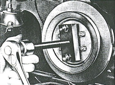
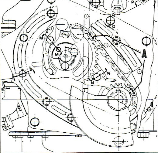
The timing chain is non-adjustable. To check for chain and sprocket wear, rotate the crankshaft until the upper span of the chain is tight. Deflection of more than ¾" from a straight line at the lower span indicates a worn chain that should be replaced. Check the sprockets for excessive wear conditions. If considerably worn, replace the sprockets.
|
INSTALLATION
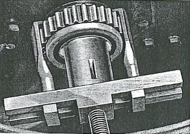
- Align keyway in crankshaft sprocket with key in crankshaft.
- Using J-5369 Installer, and with a hammer, drive crankshaft gear on until it seats against shoulder on crankshaft, Figure 19.
NOTE: After the crankshaft sprocket is installed, rotate the crankshaft until the key way is in a vertical positon at the top, Figure 20. The timing mark on the crankshaft sprocket will be approximately 60° from the vertical. (This places the #1 piston at top dead center in firing position.)
|
FIGURE 19
|
The timing chain has two punched side links 7 full lengths apart, shown as (A), Figure 20.
- Mount the timing chain on the camshaft sprocket with the marks matched on the sprocket and chain.
- Install the timing chain over the crankshaft sprocket with the chain and sprocket timing marks matched.
- Rotate the camshaft until the camshaft screw holes match those in the camshaft sprocket and install the three mounting cap screws.
- Install safety wire through the three cap screw heads.
|
FIGURE 20
|
The timing gear cover has an oil seal which fits closely over the vibration dampener hub to prebent oil leaks at the forward end of the crankshaft. The oil seal is a tight press fit in the cover and can be removed with the J-2776 Timing Gear Oil Seal Remover and Installer.
- Place the collar with the slot engaging the depression in the cover.
- Support the cover and drive the seal out with the straight side of the driver.
- Before installing a new seal, apply a coating of white or red lead in the well in the timing cover and install the oil seal in the over using the tapered side of the driver tool to rpess the seal tightly in place.
NOTE: After the seal is installed, recheck to make certain that lip of seal is in good condition.
- Use a new timing gear cover gasket and install cover assembly. Install all screws finger tight.
- With radiator off and engine raised install vibration dampener assembly (see Vibration Dampener Installation).
- Then tighten timing gear cover screws to approximately 15-20 ft. lbs.
|
NOTE: One of the six bolts attaching the pulley to the vibration dampener is offset 1/16" to insure assembly in original position, Figure 21.
REMOVAL
- Drain cooling system and remove radiator. Remove nuts from front motor support and rasie engine approsimately ½ inch.
- Remove dampener screw (1) and lock plate (2) install J-5371, Vibration Dampener Puller and remove dampener assembly.
INSTALLATION
- Align the dampener hub keyway (12) on the crankshaft.
- Using J-5369 Installer and soft hammer, install vibration dampener assembly.
- Install lock plate (2) and dampener screw (1). Tighten screw (1) to 80-90 ft. lbs.
- Lower engine, replace motor support nuts, radiator and engine coolant.
|
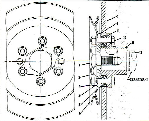 |
FIGURE 21
- Dampener cap screw.
- Dampener cap screw lock.
- Pulley attaching screw nut.
- Pulley attaching screw lockwasher.
- Dampener cushion (front).
- Dampener pulley.
- Dampener
- Dampener cover plate.
- Dampener cushion (rear).
- Pulley to dampener screw.
- Dampener hub.
- Dampener key.
|
as suggested in Hudson Service Merchandiser Vol. 6, No. 3, March 1954
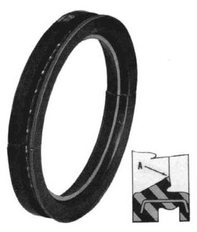
The Rear Main Bearing Oil Seal in the Jet engine is in two halves - the upper and lower - both are identical. They are installed so that the ends are perfectly flush with the parting line of the upper and lower main bearing halves. Always carefully examine the ends of seal to see that there is no part of the seal that may lap over and thus hold the main bearing cap off from a perfect sealing seat.
The seal must be installed so that the seal contact point "A," shown in the illustration [below], points in toward the engine. It is recommended that a light coat of lubriplate (part 305258) be applied to the bearing point of the seal. |
 |
REAR MAIN BEARING OIL SEAL REPLACEMENT - Engine In Car
- Drain engine oil and remove flywheel dust pan and engine oil pan.
- Remove the two bolts holding rear main bearing cap in place and loosen No. 2 and No. 3 bearing cap in place and loosen No. 2 and No. 3 bearing cap bolts 2 to 3 turns.
- using J-2955 Puller, remove No. 4 main bearing.
- Using a blunt screw driver, raise lip of oil seal at rear of crankcase, and with ¼" brass rod drive out old seal sufficiently so that end of seal can be grasped with pliers and pulled out.
- Remove oil seal from main bearing cap and clean the channel at the crankcase rear flange and in the bearing cap by forcing a swab through the channel several times and wipe dry.
- Apply a liberal amount of liquid soap to both ends of the Brummer seal and along the groove of the seal.
- Insert the end of the seal in the crankcase groove and work the seal carefully around the crankshaft until the end appears on the opposite side.
CAUTION: Exercise extreme care during seal installation to void scuffing the soft center sealing cushion at the bottom of the seal groove.
- Install the new seal in the bearing cap being careful to see that the flange on cap fits the groove in the seal.,/li>
- Apply oil liberally between the seal flange and the crankshaft journal and install rear bearing cap.
- Install the rear bearing cap bolts and tighten to 75-80 ft. lbs. torque.
- Tighten the cap screws on No. 2 and No. 3 main bearing to 75-80 ft. lbs.
- Install wicking in the grooves between the no. 4 bearing cap and crankcase, Figure 18.
Camshaft bearings are line bored in original production to close tolerance and seldom have to be replaced. If bearing clearnace becomes excessive, new bearings can be pressed in place after the camshaft and oil bearings have been removed.
Replacement bearings are available for service both reamed and unfinished. The finished bearings are sufficiently oversize to the proper dimensions when pressed into place. This eliminates the necessity of reaming or scraping bearing for proper clearance.
Service replacement camshaft bearings are a press fit of .0026" to .0055" in the cylinder block bores.
NOTE: When pressing new bearings in , always install bearings with the locating notch at the top. It is advisable to remove the engine from the car if it is necessary to replace all camshaft bearings.
CAMSHAFT REMOVAL
- Drain cooling system, remove radiator hoses and remove radiator.Remove right front wheel.
- Remove right hand fender side shield.
- Disconnect vacuum pump line, windshield wiper hose and fuel pump.
- Remove distributor.
- Remove oil pump.
- Remove valve covers and crankcase breather pipe.
- Using KMO-484 Valve Lifter, compress valve springs and raise tappets.
Hold tappets in the raised position using J-1612-3 Tappet Holders or an alternate method as outlined in the April 1951 issue of the Service Merchandiser, Page 180.
- Loosen front motor support bolt nuts and raise engine ½" to facilitate removal of dampener.
- Remove vibration dampener screw, lock plate nuts and lock plate and pull off dampener with Puller J-5371.
- Remove dampener key and gear case cover.
- Align gear markings and remove camshaft sprocket, chain and crankshaft sprocket using tool J-471.
NOTE: Before the camshaft is removed from the block, end play should be checked. The range should be .003" to .005". With a pry bar, move the camshaft toward the rear of the engine. Check between the camshaft forward bearing and thrust plate with a feeler gauge. If end play is more than .010", replace the thrust plate.
- Remove camshaft and thrust washer.
NOTE: The camshaft can be removed between the grille louvres, rotate the camshaft and withdraw slowly and carefully to prevent camshaft or bearing damage.
INSTALLATION
To install, reverse procedure of removal.
NOTE: Timing chain and sprockets should be installed with No. 1 piston on top dead center with marks on sprockets 7 links or 14 inches apart as shown in Figure 20.
The valve lash should be set at .010 on the intake and .012 on the exhaust for checking the timing events, if the dial gauge on the valve head is to be used to indicated the point of opening and closing. If the points of opening and closing are to be determined by the use of feeler gauge the valve lash should be increased from the above dimensions by the thickness of the feeler gauge used.
The timing events in crankshaft angles are as follows:
Intake Opens
Intake Closes
Exhaust Opens
Exhaust Closes | 26.8° BTC
99.7° ABC
64.9° BBC
45.7° ATC |
The above figures are for a new engine. The initial chain stretch which occurs within the first 5,000 miles of driving is usually sufficient to retard the events approximately 2°.
|
VALVE TIMING CHECK
[Italicized portion is in addition to manual as suggested in Hudson Service Merchandiser, Vol. 5, No. 5, May 1953]
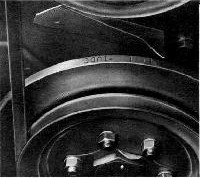
All Jet engines have the valve timing and spark setting marking on the periphery of the vibration dampener, with a poiner spot welded to the timing chain cover, as shown in the illustration.
To determine if valve timing is correct without disassembly work, the following procedure may be used. |
 |
- Remove the front tappet cover and adjust the tappet clearnace of number one intake valbe to .010" with the engine hot or .012" on a cold engine.
- Insert a .002" feeler gauge between number one intake tappet adjusting screw and end of valbe stem, then turn crankshaft slowly (by pulling on the lowermost fan blade) in direction of rotation until the exhaust valve begins to close. Continue turning crankshaft very slowly until a light drag is felt on the feeler gauge.
- At this point, inspect the timing marks on the dampener. the engine is correctly timed when the No. 1 UDC mark (long mark) is one inch from the pointer. This would show the first short mark 1/4 inch before the pointer.
- Reset No. 1 intake valave to recommended clearance of .010" hot or .012" cold and reinstall tappet cover.
If valve tappets, with proper clearance, are noisy the following should be checked:
- Tappets loose in their guides.
- Tappets not properly rotating, causing uneven wear on tappet faces.
- Weak valve springs.
- Valve sticking in valve guides.
- Valves loose in valve guides.
- Valve springs cocked or not seating properly.
- Warped valve.
- Valve seat and guide not in alignment.
Where can I find replacement motor mounts for my Jet?
There are a few options. The rear mount is the universal one used in all '32 - '54 models. The front ones can be adapted from generic mounts the same thickness, with studs top and bottom. Just make up a plate to go across the chassis at the bottom and bolt it to the frame, and drill a hole for the bottom stud. Another option for front motor mounts someone suggested is going to NAPA and purchasing Belkamp 602-1054, however, I can't confirm that this indeed works. Also, look below at the Replacement Parts section for more options on both front and rear mounts.
Front Engine Mount: (possibly) NAPA: Belkamp 602-1054
Rear Engine Mount: BorgWarner #31-2215
Oil Pressure Switch: NAPA Echlin OP 6415, Stewart Warner D364L
Timing Chain: Cloytes C-345, NAPA Microtest 9-345, TRW #TC 339
|
|
|
|
|
Courtesy HET JetSet - All Rights Reserved.
|
|